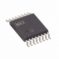
MAX1415EUE+ Maxim Integrated Products, MAX1415EUE+ Datasheet - Page 18

MAX1415EUE+
Manufacturer Part Number
MAX1415EUE+
Description
IC ADC 16BIT DELTA SIGMA 16TSSOP
Manufacturer
Maxim Integrated Products
Datasheet
1.MAX1415EUE.pdf
(36 pages)
Specifications of MAX1415EUE+
Number Of Bits
16
Sampling Rate (per Second)
500
Data Interface
MICROWIRE™, QSPI™, Serial, SPI™
Number Of Converters
1
Power Dissipation (max)
755mW
Voltage Supply Source
Single Supply
Operating Temperature
-45°C ~ 85°C
Mounting Type
Surface Mount
Package / Case
16-TSSOP
Lead Free Status / RoHS Status
Lead free / RoHS Compliant
16-Bit, Low-Power, 2-Channel,
Sigma-Delta ADCs
18
______________________________________________________________________________________
PIN
10
11
12
13
14
15
16
1
2
3
4
5
6
7
8
9
CLKOUT
RESET
NAME
CLKIN
AIN2+
AIN1+
DOUT
DRDY
SCLK
AIN1-
REF+
AIN2-
GND
REF-
V
DIN
CS
DD
Serial Clock Input. Apply an external serial clock to transfer data to and from the device at data rates
up to 5MHz.
Clock Input. Connect a crystal/resonator between CLKIN and CLKOUT, or drive CLKIN externally with
a CMOS-compatible clock source. Connect CLKIN to GND when using the internal oscillator.
Clock Output. Connect a crystal/resonator between CLKIN and CLKOUT. When enabled, CLKOUT
provides a CMOS-compatible, inverted clock output. CLKOUT can drive one CMOS load. Set CLKDIS
= 0 in the clock register to enable CLKOUT. Set CLKDIS = 1 in the clock register to disable CLKOUT.
Active-Low Chip-Select Input. CS selects the active device in systems with more than one device on
the serial bus. Drive CS low to clock data in on DIN and to clock data out on DOUT. When CS is high,
DOUT is high impedance. Connect CS to GND for 3-wire operation.
Active-Low Reset Input. Drive RESET low to reset the MAX1415/MAX1416 to power-on reset status.
Channel 2 Positive Analog Input
Channel 1 Positive Analog Input
Channel 1 Negative Analog Input
Positive Reference Input
Negative Reference Input
Channel 2 Negative Analog Input
Active-Low Data Ready Output. DRDY goes low when a new conversion result is available in the data
register. When a read operation of a full output word completes, DRDY returns high.
Serial Data Output. DOUT outputs serial data from the data register. DOUT changes on the falling
edge of SCLK and is valid on the rising edge of SCLK. When CS is high, DOUT is high impedance.
Serial Data Input. Data on DIN is clocked in on the rising edge of SCLK when CS is low.
Power Input. Connect V
4.75V to 5.25V power supply for the MAX1416.
Ground
DD
to a 2.7V to 3.6V power supply for the MAX1415, and connect V
FUNCTION
Pin Description
DD
to a


