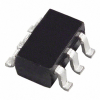
AD7466BRTZ-R2 Analog Devices Inc, AD7466BRTZ-R2 Datasheet - Page 21

AD7466BRTZ-R2
Manufacturer Part Number
AD7466BRTZ-R2
Description
IC ADC 12BIT 1.6V LP SOT23-6
Manufacturer
Analog Devices Inc
Specifications of AD7466BRTZ-R2
Data Interface
DSP, MICROWIRE™, QSPI™, Serial, SPI™
Design Resources
Software Calibrated, 50 MHz to 9 GHz, RF Power Measurement System (CN0178)
Number Of Bits
12
Sampling Rate (per Second)
200k
Number Of Converters
1
Power Dissipation (max)
900µW
Voltage Supply Source
Single Supply
Operating Temperature
-40°C ~ 85°C
Mounting Type
Surface Mount
Package / Case
SOT-23-6
Resolution (bits)
12bit
Sampling Rate
200kSPS
Input Channel Type
Single Ended
Supply Voltage Range - Analog
1.6V To 3.6V
Supply Current
300µA
Lead Free Status / RoHS Status
Lead free / RoHS Compliant
For Use With
EVAL-AD7466CBZ - BOARD EVALUATION FOR AD7466
Lead Free Status / RoHS Status
Lead free / RoHS Compliant, Lead free / RoHS Compliant
Available stocks
Company
Part Number
Manufacturer
Quantity
Price
Part Number:
AD7466BRTZ-R2
Manufacturer:
ADI/亚德诺
Quantity:
20 000
Figure 18 shows power consumption vs. throughput rate for a
3.4 MHz SCLK frequency. In this case, the conversion time is
the same for all cases because the SCLK frequency is a fixed
parameter. Low throughput rates lead to lower current con-
sumptions, with a higher percentage of the time in power-down
mode. Figure 27 shows two AD7466s running with the same
SCLK frequency, but at different throughput rates. The A
throughput rate is higher than the B throughput rate. The
slower the throughput rate, the longer the period of time the
part is in power-down mode, and the average power consump-
tion drops accordingly.
Figure 28 shows the power vs. throughput rate for different
supply voltages and SCLK frequencies. For this plot, all the
elements regarding power consumption that were explained
previously (the influence of the SCLK frequency, the influence
of the throughput rate, and the influence of the supply voltage)
are taken into consideration.
The following examples show calculations for the information
in this section.
Power Consumption Example 1
This example shows that, for a fixed throughput rate, as the
SCLK frequency increases, the average power consumption
drops. From Figure 26, for SCLK A = 3.4 MHz, SCLK B =
1.2 MHz, and a throughput rate of 50 kSPS, which gives a cycle
time of 20 μs, the following values can be obtained:
Conversion Time A = 16 × (1/SCLK A) = 4.7 μs
(23.5% of the cycle time)
Power-Down Time A = (1/Throughput) − Conversion
Time A = 20 μs − 4.7 μs = 15.3 μs (76.5% of the cycle time)
Conversion Time B = 16 × (1/SCLK B) = 13 μs
(65% of the cycle time)
Power-Down Time B = (1/Throughput) − Conversion
Time B = 20 μs − 13 μs = 7 μs (35% of the cycle time)
1.4
1.2
1.0
0.8
0.6
0.4
0.2
0
0
TEMP = 25°C
V
DD
= 3.0V, SCLK = 2.4MHz
for Different SCLK and Supply Voltages
Figure 28. Power vs. Throughput Rate
50
THROUGHPUT (kSPS)
V
100
DD
= 1.8V, SCLK = 2.4MHz
V
V
DD
DD
150
= 1.8V, SCLK = 3.4MHz
= 3.0V, SCLK = 3.4MHz
200
250
Rev. C | Page 21 of 28
The average power consumption includes the power dissipated
when the part is converting and the power dissipated when the
part is in power-down mode. The average power dissipated
during conversion is calculated as the percentage of the cycle
time spent when converting, multiplied by the maximum
current during conversion. The average power dissipated in
power-down mode is calculated as the percentage of cycle time
spent in power-down mode, multiplied by the current figure for
power-down mode. In order to obtain the value for the average
power, these terms must be multiplied by the voltage.
Considering the maximum current for each SCLK frequency
for V
It can be concluded that for a fixed throughput rate, the average
power consumption drops as the SCLK frequency increases.
Power Consumption Example 2
This example shows that, for a fixed SCLK frequency, as the
throughput rate decreases, the average power consumption
drops. From Figure 27, for SCLK = 3.4 MHz, Throughput A =
100 kSPS (which gives a cycle time of 10 μs), and Throughput B
= 50 kSPS (which gives a cycle time of 20 μs), the following
values can be obtained:
The average power consumption is calculated as explained in
Power Consumption Example 1, considering the maximum
current for a 3.4 MHz SCLK frequency for V
It can be concluded that for a fixed SCLK frequency, the average
power consumption drops as the throughput rate decreases.
Power Consumption A = ((4.7/20) × 186 μA + (15.3/20) ×
100 nA) × 1.8 V = (43.71 + 0.076) μA × 1.8 V = 78.8 μW
= 0.07 mW
Power Consumption B = ((13/20) × 108 μA + (7/20) ×
100 nA) × 1.8 V = (70.2 + 0.035) μA × 1.8 V = 126.42 μW
= 0.126 mW
Conversion Time A = 16 × (1/SCLK) = 4.7 μs
(47% of the cycle time for a throughput of 100 kSPS)
Power-Down Time A = (1/Throughput A) − Conversion
Time A = 10 μs − 4.7 μs = 5.3 μs (53% of the cycle time)
Conversion Time B = 16 × (1/SCLK) = 4.7 μs
(23.5% of the cycle time for a throughput of 50 kSPS)
Power-Down Time B = (1/Throughput B) − Conversion
Time B = 20 μs − 4.7 μs = 15.3 μs (76.5% of the cycle time)
Power Consumption A = ((4.7/10) × 186 μA + (5.3/10) ×
100 nA) × 1.8 V= (87.42 + 0.053) μA × 1.8 V = 157.4 μW =
0.157 mW
Power Consumption B = ((4.7/20) × 186 μA + (15.3/20) ×
100 nA) × 1.8 V = (43.7 + 0.076) μA × 1.8 V = 78.79 μW =
0.078 mW
DD
= 1.8 V,
AD7466/AD7467/AD7468
DD
= 1.8 V.


