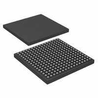
AD6654BBC Analog Devices Inc, AD6654BBC Datasheet - Page 36

AD6654BBC
Manufacturer Part Number
AD6654BBC
Description
IC ADC 14BIT W/6CH RSP 256CSPBGA
Manufacturer
Analog Devices Inc
Datasheet
1.AD6654CBCZ.pdf
(88 pages)
Specifications of AD6654BBC
Number Of Bits
14
Sampling Rate (per Second)
92.16M
Data Interface
Serial, Parallel
Number Of Converters
1
Power Dissipation (max)
2.5W
Voltage Supply Source
Analog and Digital
Operating Temperature
-25°C ~ 85°C
Mounting Type
Surface Mount
Package / Case
256-CSPBGA
Lead Free Status / RoHS Status
Contains lead / RoHS non-compliant
Available stocks
Company
Part Number
Manufacturer
Quantity
Price
Company:
Part Number:
AD6654BBC
Manufacturer:
AD
Quantity:
13 888
Company:
Part Number:
AD6654BBC
Manufacturer:
ADI
Quantity:
280
Company:
Part Number:
AD6654BBC
Manufacturer:
Analog Devices Inc
Quantity:
10 000
Part Number:
AD6654BBC
Manufacturer:
ADI/亚德诺
Quantity:
20 000
Company:
Part Number:
AD6654BBCZ
Manufacturer:
ADI
Quantity:
853
Company:
Part Number:
AD6654BBCZ
Manufacturer:
Analog Devices Inc
Quantity:
10 000
AD6654
FIFTH-ORDER CIC FILTER
The signal processing stage immediately after the NCO is a CIC
filter stage. This stage implements a fixed coefficient, decimat-
ing, cascade integrated comb filter. The input rate to this filter is
the same as the data rate at the input port; the output rate from
this stage is dependent on the decimation factor.
The decimation ratio, M
(only integer values). The 5-bit word in the CIC decimation
register is used to set the CIC decimation factor. A binary value
of one less than the decimation factor is written into this
register. The decimation ratio of 1 can be achieved by bypassing
the CIC filter stage. The frequency response of the filter is given
by the following equations. The gain and pass-band droop of
the CIC should be calculated by these equations. Both parame-
ters can be offset in the RCF stage.
where:
f
S
between 0 and 20.
The attenuation of the data into the CIC stage should be con-
trolled in 6 dB increments. For the best dynamic range, S
should be set to the smallest value possible (lowest attenuation
possible) without creating an overflow condition. This can be
accomplished safely using the following equation, where
input_level is the largest possible fraction of the full-scale value
at the input port. This value is output from the NCO stage and
pipelined into the CIC filter.
BYPASS
The fifth-order CIC filter can be bypassed when no decimation
is required of it. When it is bypassed, the scaling operation is
IN
CIC
is the data input rate to the channel under consideration.
, the scale factor, is a programmable unsigned integer
OL
H
H
S
f
CIC
CIC
(
(
z
f
CIC
)
)
=
=
=
=
ceil
=
2
M
2
f
(
(
S
(
S
2
IN
CIC
CIC
M
CIC
(
1
S
log
1
CIC
CIC
+
+
5
2
)
) 5
+
(
5
×
5
M
)
×
⎛
⎜
⎜
⎝
CIC
×
CIC
⎛
⎜
⎜
⎜
⎜
⎜
⎜
⎝
1
input
, can be programmed from 2 to 32
SIN
−
1
SIN
5
Z
−
×
−
⎛
⎜
⎜
⎝
Z
input
M
M
⎛
⎜
⎜
⎝
−
_
π
CIC
1
level
CIC
f
f
IN
IN
f
⎞
⎟
⎟
⎠
_
×
5
level
f
⎞
⎟
⎟
⎠
⎞
⎟
⎟
⎠
⎞
⎟
⎟
⎟
⎟
⎟
⎟
⎠
)
5
)
−
5
CIC
Rev. 0 | Page 36 of 88
not performed. In bypass mode, the output of the CIC filter is
the same as the input of the CIC filter.
CIC REJECTION
Table 15 illustrates the amount of bandwidth as a percentage of
the data rate into the CIC stage, which can be protected with
various decimation rates and alias rejection specifications. The
maximum input rate into the CIC is 150 MHz (the same as the
maximum input port data rate). The data can be scaled to any
other allowable sample rate.
Table 15 can be used to decide the minimum decimation
required in the CIC stage to preserve a certain bandwidth. The
CIC5 stage can protect a much wider bandwidth to any given
rejection, when a decimation ratio lower than that identified in
the table is used. The table helps to calculate an upper boundary
on decimation, M
Table 15. SSB CIC5 Alias Rejection Table (f
MCIC5
2
3
4
5
6
7
8
9
10
11
12
13
14
15
16
17
18
19
20
21
22
23
24
25
26
27
28
29
30
31
32
−60 dB
8.078
6.367
5.022
4.107
3.463
2.989
2.627
2.342
2.113
1.924
1.765
1.631
1.516
1.416
1.328
1.250
1.181
1.119
1.064
1.013
0.967
0.925
0.887
0.852
0.819
0.789
0.761
0.734
0.710
0.687
0.666
CIC
, given the desired filter characteristics.
−70 dB
6.393
5.110
4.057
3.326
2.808
2.425
2.133
1.902
1.716
1.563
1.435
1.326
1.232
1.151
1.079
1.016
0.960
0.910
0.865
0.824
0.786
0.752
0.721
0.692
0.666
0.641
0.618
0.597
0.577
0.559
0.541
−80 dB
5.066
4.107
3.271
2.687
2.270
1.962
1.726
1.540
1.390
1.266
1.162
1.074
0.998
0.932
0.874
0.823
0.778
0.737
0.701
0.667
0.637
0.610
0.584
0.561
0.540
0.520
0.501
0.484
0.468
0.453
0.439
−90 dB
4.008
3.297
2.636
2.170
1.836
1.588
1.397
1.247
1.125
1.025
0.941
0.870
0.809
0.755
0.708
0.667
0.630
0.597
0.568
0.541
0.516
0.494
0.474
0.455
0.437
0.421
0.406
0.392
0.379
0.367
0.355
IN
= 1)
−100 dB
3.183
2.642
2.121
1.748
1.480
1.281
1.128
1.007
0.909
0.828
0.760
0.703
0.653
0.610
0.572
0.539
0.509
0.483
0.459
0.437
0.417
0.399
0.383
0.367
0.353
0.340
0.328
0.317
0.306
0.297
0.287


