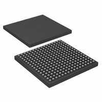
AD6654BBC Analog Devices Inc, AD6654BBC Datasheet - Page 45

AD6654BBC
Manufacturer Part Number
AD6654BBC
Description
IC ADC 14BIT W/6CH RSP 256CSPBGA
Manufacturer
Analog Devices Inc
Datasheet
1.AD6654CBCZ.pdf
(88 pages)
Specifications of AD6654BBC
Number Of Bits
14
Sampling Rate (per Second)
92.16M
Data Interface
Serial, Parallel
Number Of Converters
1
Power Dissipation (max)
2.5W
Voltage Supply Source
Analog and Digital
Operating Temperature
-25°C ~ 85°C
Mounting Type
Surface Mount
Package / Case
256-CSPBGA
Lead Free Status / RoHS Status
Contains lead / RoHS non-compliant
Available stocks
Company
Part Number
Manufacturer
Quantity
Price
Company:
Part Number:
AD6654BBC
Manufacturer:
AD
Quantity:
13 888
Company:
Part Number:
AD6654BBC
Manufacturer:
ADI
Quantity:
280
Company:
Part Number:
AD6654BBC
Manufacturer:
Analog Devices Inc
Quantity:
10 000
Part Number:
AD6654BBC
Manufacturer:
ADI/亚德诺
Quantity:
20 000
Company:
Part Number:
AD6654BBCZ
Manufacturer:
ADI
Quantity:
853
Company:
Part Number:
AD6654BBCZ
Manufacturer:
Analog Devices Inc
Quantity:
10 000
CHANNEL RAM COEFFICIENT FILTER (CRCF)
Following the DRCF is the programmable decimating CRCF
FIR filter. The only difference between the DRCF and CRCF
filters is the coefficient bit width. The DRCF has 14-bit
coefficients, while the CRCF has 20-bit coefficients.
This filter can calculate up to 64 asymmetrical filter taps or up
to 128 symmetrical filter taps. The filter is capable of a
programmable decimation rate from 1 to 16. The flexible
coefficient offset feature allows loading multiple filters into the
coefficient RAM and changing the filters on the fly. The
decimation phase feature allows for a polyphase implementa-
tion in which multiple AD6654 channels are used to process a
single carrier.
The CRCF filter has 20-bit input and output data and 20-bit
coefficient data. The number of filter taps to calculate is
programmable and is set in the CRCF taps register. The value
of the number of taps minus one is written to this register. For
example, a value of 19 in the register corresponds to 20 filter
taps. The decimation rate is programmable using the 4-bit
CRCF decimation rate word in the CRCF control register.
Again, the value written is the decimation rate minus one.
BYPASS
The CRCF filter can be used in normal operation or bypassed
using the CRCF bypass bit in the CRCF control register. When
the CRCF filter is bypassed, no scaling is applied and the output
of the filter is the same as the input to the CRCF filter.
SCALING
The output of the CRCF filter can be scaled using the 2-bit
CRCF scaling word in the CRCF control register. Table 22
shows the valid values for the 2-bit word and the corresponding
settings. | ∑
form) used to calculate the FIR filter.
Table 22. CRCF Scaling Factor Settings
CRCF Scale Word[1:0]
00
01
10
11
SYMMETRY
The CRCF filter does not require symmetrical filters. However,
if the filter is symmetrical, then the symmetry bit in the CRCF
control register should be set. When this bit is set, only half the
impulse response needs to be programmed into the CRCF
coefficient memory registers. For example, if the number of
filter taps is equal to 15 or 16 and the filter is symmetric, then
only eight coefficients need to be written into the coefficient
memory.
COEFF
| is the sum of all coefficients (in normalized
Scaling Factor
18.06 dB attenuation
12.04 dB attenuation
6.02 dB attenuation
No scaling, 0 dB
Rev. 0 | Page 45 of 88
Because a total of 64 taps can be written into the memory
registers, the CRCF can perform 64 asymmetrical filter taps or
128 symmetrical filter taps.
COEFFICIENT OFFSET
More than one set of filter coefficients can be loaded into the
coefficient RAM at any time (given sufficient RAM space). The
coefficient offset can be used in this case to access the two or
more different filters. By changing the coefficient offset, the
filter coefficients being accessed can be changed on the fly.
This decimal offset value is programmed in the CRCF
coefficient offset register. When this value is changed during
the calculation of a particular output data sample, the sample
calculation is completed using the old coefficients and the new
coefficient offset is brought into effect from the next data
sample calculation.
DECIMATION PHASE
When more than one channel of the AD6654 is used to process
one carrier, polyphase implementation of the corresponding
channels’ DRCF or CRCF is possible using the decimation
phase feature. This feature can be used only under certain
conditions. The decimation phase is programmed using the
4-bit CRCF decimation phase word of the CRCF control
register.
MAXIMUM NUMBER OF TAPS CALCULATED
The output rate of the CRCF filter is given by
where:
f
filter.
M
The CRCF filter consists of two multipliers (one each for the
I and Q paths). Each multiplier, working at the high speed clock
rate (PLL clock), can multiply (or tap once). Therefore, the
maximum number of filter taps that can be calculated
(symmetrical or asymmetrical filter) is given by
f
the PLL clock multiplier.
f
calculated.
DRCF
PLLCLK
CRCF
CRCF
is the output rate of the CRCF filter as previously
is the data rate out of the DRCF filter and into the CRCF
Maximum Number of Taps = ceil
f
is the decimation rate in the CRCF filter.
is the high speed internal processing clock generated by
CRCF
=
M
f
DRCF
CRCF
⎛
⎜
⎜
⎝
f
PLLCLK
f
CRCF
⎞
⎟
⎟
⎠
− 1
AD6654


