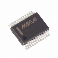
MAX113CAG+T Maxim Integrated Products, MAX113CAG+T Datasheet - Page 6

MAX113CAG+T
Manufacturer Part Number
MAX113CAG+T
Description
IC ADC 8BIT 400KSPS 24-SSOP
Manufacturer
Maxim Integrated Products
Datasheet
1.MAX113CAG.pdf
(12 pages)
Specifications of MAX113CAG+T
Number Of Bits
8
Sampling Rate (per Second)
400k
Data Interface
Parallel
Number Of Converters
3
Power Dissipation (max)
640mW
Voltage Supply Source
Single Supply
Operating Temperature
0°C ~ 70°C
Mounting Type
Surface Mount
Package / Case
24-SSOP
Lead Free Status / RoHS Status
Lead free / RoHS Compliant
+3V, 400ksps, 4/8-Channel,
8-Bit ADCs with 1µA Power-Down
6
______________________________________________________________Pin Description
17, 18, 19
MAX113
7, 8, 9
_______________________________________________________________________________________
10
11
12
13
14
15
16
20
21
22
23
24
—
—
—
—
1
2
3
4
5
6
PIN
19, 20, 21
MAX117
9, 10, 11
12
13
14
15
16
17
18
22
23
24
25
26
27
28
1
2
3
4
5
6
7
8
D1, D2, D3
D4, D5, D6
WR/RDY
PWRDN
NAME
MODE
REF+
GND
REF-
V
IN6
IN5
IN4
IN3
IN2
IN1
INT
IN7
D0
RD
CS
D7
A2
A1
A0
DD
Analog Input Channel 6
Analog Input Channel 5
Analog Input Channel 4
Analog Input Channel 3
Analog Input Channel 2
Analog Input Channel 1
Mode Selection Input. Internally pulled low with a 15µA current source. MODE = 0
activates read mode; MODE = 1 activates write-read mode (see Digital Interface
section).
Three-State Data Output (LSB)
Three-State Data Outputs
Read Input. RD must be low to access data (see Digital Interface section).
Interrupt Output. INT goes low to indicate end of conversion (see Digital Interface
section).
Ground
Lower limit of reference span. REF- sets the zero-code voltage. Range is GND ≤
V
Upper limit of reference span. REF+ sets the full-scale input voltage. Range is
V
Write-Control Input/Ready-Status Output (see Digital Interface section)
Chip-Select Input. CS must be low for the device to recognize WR or RD inputs.
Three-State Data Outputs
Three-State Data Output (MSB)
Multiplexer Channel Address Input (MSB)
Multiplexer Channel Address Input
Multiplexer Channel Address Input (LSB)
Power-Down Input. PWRDN reduces supply current when low.
Positive Supply, +3.0V to +3.6V
Analog Input Channel 7
REF-
REF-
< V
< V
REF+
REF+
.
≤ V
DD
. Internally hardwired to IN8 (Table 1).
FUNCTION


