HI5714/4CB Intersil, HI5714/4CB Datasheet - Page 4
HI5714/4CB
Manufacturer Part Number
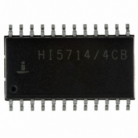
HI5714/4CB
Description
IC ADC 8-BIT 40MSPS 24-SOIC
Manufacturer
Intersil
Datasheet
1.HI57144CBZ.pdf
(14 pages)
Specifications of HI5714/4CB
Number Of Bits
8
Sampling Rate (per Second)
40M
Data Interface
Parallel
Number Of Converters
1
Power Dissipation (max)
375mW
Voltage Supply Source
Analog and Digital
Operating Temperature
0°C ~ 70°C
Mounting Type
Surface Mount
Package / Case
24-SOIC (0.300", 7.50mm Width)
Lead Free Status / RoHS Status
Contains lead / RoHS non-compliant
Available stocks
Company
Part Number
Manufacturer
Quantity
Price
Company:

Part Number:
HI5714/4CB
Manufacturer:
INTERSIL
Quantity:
162
Part Number:
HI5714/4CB
Manufacturer:
HARRIS
Quantity:
20 000


Electrical Specifications
DIGITAL OUTPUTS (D0 to D7 and O/UF Referenced to OGND)
Logic Output Voltage Low, V
Logic Output Voltage High, V
Output Leakage Current, I
SWITCHING CHARACTERISTICS (Notes 4, 5) See Figure 1
Sample Rate, f
Clock Pulse Width High, t
Clock Pulse Width Low, t
ANALOG SIGNAL PROCESSING (f
Differential Gain, DG
Differential Phase, DP
HARMONICS (f
Second Harmonic, H2
Third Harmonic, H3
Total Harmonic Distortion, THD
Spurious Free Dynamic Range, SFDR
Analog Input Bandwidth (-3dB)
TRANSFER FUNCTION
Differential Linearity Error, DNL
Integral Linearity Error, INL
EFFECTIVE NUMBER OF BITS
ENOB
Bit Error Rate, BER
TIMING (f
Sampling Delay, t
Output Hold Time, t
Output Delay Time, t
Output Enable Delay, t
Output Enable Delay, t
Output Disable Delay, t
Output Disable Delay, t
Aperture Jitter, t
HI5714/7
HI5714/4
HI5714/4 (f
HI5714/7 (f
CLK
CLK
CLK
CLK
= 75MHz) See Figures 1, 2
AJ
CLK
SD
= 40MHz)
= 75MHz)
HD
PARAMETER
D
= 75MHz)
PZH
PZL
PHZ
PLZ
CPL
CPH
D
OL
OH
4
V
CCA
CLK
= V
= 40MHz)
CCD
= V
CCO
I
I
0.4V < V
(Notes 6, 9)
(Notes 6, 9)
f
f
f
f
(Note 7)
(Note 7)
f
f
f
f
f
(Note 8)
HI5714/4/7
Enable to High
Enable to Low
Disable from High
Disable from Low
O
O
IN
IN
IN
IN
IN
IN
IN
IN
IN
= +5V; V
= 1mA
= -0.4mA
= 4.43MHz
= 4.43MHz
= 4.43MHz
= 4.43MHz
= 4.43MHz
= 7.5MHz
= 4.43MHz
= 7.5MHz
= 10MHz
OUT
TEST CONDITION
HI5714
RB
= 1.3V; V
< V
CCO
RT
= 3.6V; T
A
= 25
o
C, Unless Otherwise Specified (Continued)
MIN
-20
2.7
75
40
0
6
6
5
-
-
-
-
-
-
-
-
-
-
-
-
-
-
-
-
-
-
-
-
-
-
± 0.75
10
TYP
0.05
± 0.4
7.65
7.15
14.6
17.8
1.0
-63
-65
-59
7.5
7.4
6.8
5.3
6.7
62
18
10
50
-
-
-
-
-
-
-
-
-
-11
V
MAX
+20
0.4
CCO
13
2
-
-
-
-
-
-
-
-
-
-
-
-
-
-
-
-
-
-
-
-
-
-
-
-
-
Sample
degree
UNITS
Times/
MHz
MHz
MHz
LSB
LSB
Bits
Bits
Bits
Bits
Bits
µA
dB
dB
dB
dB
ns
ns
ns
ns
ns
ns
ns
ns
ns
ps
%
V
V
Related parts for HI5714/4CB
Image
Part Number
Description
Manufacturer
Datasheet
Request
R

Part Number:
Description:
CONV A/D 8BIT PREC 24-SOIC
Manufacturer:
Intersil
Datasheet:

Part Number:
Description:
Manufacturer:
Intersil Corporation
Datasheet:

Part Number:
Description:
IC ADC 8-BIT 40MSPS 24-SOIC
Manufacturer:
Intersil
Datasheet:

Part Number:
Description:
CONV A/D 8BIT 75MSPS 24-SOIC
Manufacturer:
Intersil
Datasheet:
Part Number:
Description:
8-bit, 40/60/75/80 Msps A/d Converter
Manufacturer:
Intersil Corporation
Datasheet:

Part Number:
Description:
8-Bit, 40/60/75/80 MSPS A/D Converter
Manufacturer:
INTERSIL [Intersil Corporation]
Datasheet:
Part Number:
Description:
Intersil Corporation [CMOS Serial Controller Interface]
Manufacturer:
Intersil Corporation
Datasheet:
Part Number:
Description:
Manufacturer:
Intersil Corporation
Datasheet:
Part Number:
Description:
357-036-542-201 CARDEDGE 36POS DL .156 BLK LOPRO
Manufacturer:
Intersil Corporation
Datasheet:
Part Number:
Description:
1024-Word x 4-Bit LSI Static RAM
Manufacturer:
Intersil Corporation
Datasheet:
Part Number:
Description:
General Purpose NPN Transistor Arrays FN341.4
Manufacturer:
Intersil Corporation
Datasheet:
Part Number:
Description:
CMOS 16-Bit Microprocessor
Manufacturer:
Intersil Corporation
Datasheet:
Part Number:
Description:
Manufacturer:
Intersil Corporation
Datasheet:
Part Number:
Description:
Manufacturer:
Intersil Corporation
Datasheet:
Part Number:
Description:
Manufacturer:
Intersil Corporation
Datasheet: