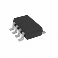
AD5228BUJZ10-R2 Analog Devices Inc, AD5228BUJZ10-R2 Datasheet - Page 11

AD5228BUJZ10-R2
Manufacturer Part Number
AD5228BUJZ10-R2
Description
IC DGTL POT 10K UP/DN TSOT23-8
Manufacturer
Analog Devices Inc
Datasheet
1.AD5228BUJZ10-RL7.pdf
(20 pages)
Specifications of AD5228BUJZ10-R2
Taps
32
Resistance (ohms)
10K
Number Of Circuits
1
Temperature Coefficient
35 ppm/°C Typical
Memory Type
Volatile
Interface
Up/Down Counter
Voltage - Supply
2.7 V ~ 5.5 V
Operating Temperature
-40°C ~ 105°C
Mounting Type
Surface Mount
Package / Case
TSOT-23-8, TSOT-8
Resistance In Ohms
10K
End To End Resistance
10kohm
Track Taper
Linear
No. Of Steps
32
Resistance Tolerance
± 20%
Supply Voltage Range
2.7V To 5.5V
Control Interface
Pushbutton
No. Of Pots
Single
Lead Free Status / RoHS Status
Lead free / RoHS Compliant
For Use With
EVAL-AD5228EBZ - BOARD EVAL FOR AD5228 DGTL POT
Lead Free Status / Rohs Status
Compliant
THEORY OF OPERATION
The AD5228 is a 32-position manual up/down digitally con-
trolled potentiometer with selectable power-on preset. The
AD5228 presets to midscale when the PRE pin is tied to ground
and to zero-scale when PRE is tied to V
is not allowed. The step-up and step-down operations require
the activation of the PU (push-up) and PD (push-down) pins.
These pins have 100 kΩ internal pull-up resistors that the PU
and PD activate at logic low. The common practice is to apply
external pushbuttons (tactile switches) as shown in
Because of the bounce mechanism commonly found in the
switches during contact closures, a single pushbutton press
usually generates numerous bounces during contact closure.
Note that the term pushbutton refers specifically to a
pushbutton tactile switch or a similar switch that has 10 ms or
less bounce time during contact closure. Figure 31 shows the
characteristics of one such switch, the KRS-3550 tactile switch.
Figure 32 and Figure 33 show close ups of the initial bounces
and end bounces, respectively.
PUSH-DOWN
PUSH-UP
1
BUTTON
BUTTON
CH1
1.00V
Figure 31. Typical Tactile Switch Characteristics
V
PU
PD
Figure 30. Typical Pushbutton Interface
DD
R1
R2
SCAN DETECT
DEBOUNCER
STEP/AUTO
CONTROL
DISCRETE
ADAPTIVE
UP/DOWN
M40.0ms
T
LOGIC
20.40%
DD
. Floating the PRE pin
PRE
A CH1
D
E
C
O
D
E
SCALE PRESET
ZERO- OR MID-
AD5228
Figure 30
2.38V
GND
Rev. A | Page 11 of 20
.
A
W
B
The following paragraphs describes the PU incrementing
operation. Similar characteristics apply to the PD decrementing
operation.
The AD5228 features an adaptive debouncer that monitors the
duration of the logic-low level of PU signal between bounces. If
the PU logic-low level signal duration is shorter than 7 ms, the
debouncer ignores it as an invalid incrementing command.
Whenever the logic-low level of PU signal lasts longer than
11 ms, the debouncer assumes that the last bounce is met and
therefore increments R
Repeatedly pressing the PU button for fast adjustment without
missing steps is allowed, provided that each press is not shorter
than t
an advanced video game player can press a pushbutton switch
in 40 ms.
PU
1
1
, which is 12 ms (see
CH1
CH1
1.00V
1.00V
Figure 32. Close-Up of Initial Bounces
Figure 33. Close-Up of Final Bounces
WB
by one step.
Figure 2
M100μs
M10.0μs
T
T
20.20%
20.20%
). As a point of reference,
A CH1
A CH1
2.38V
2.38V
AD5228


