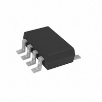
AD5228BUJZ10-R2 Analog Devices Inc, AD5228BUJZ10-R2 Datasheet - Page 12

AD5228BUJZ10-R2
Manufacturer Part Number
AD5228BUJZ10-R2
Description
IC DGTL POT 10K UP/DN TSOT23-8
Manufacturer
Analog Devices Inc
Datasheet
1.AD5228BUJZ10-RL7.pdf
(20 pages)
Specifications of AD5228BUJZ10-R2
Taps
32
Resistance (ohms)
10K
Number Of Circuits
1
Temperature Coefficient
35 ppm/°C Typical
Memory Type
Volatile
Interface
Up/Down Counter
Voltage - Supply
2.7 V ~ 5.5 V
Operating Temperature
-40°C ~ 105°C
Mounting Type
Surface Mount
Package / Case
TSOT-23-8, TSOT-8
Resistance In Ohms
10K
End To End Resistance
10kohm
Track Taper
Linear
No. Of Steps
32
Resistance Tolerance
± 20%
Supply Voltage Range
2.7V To 5.5V
Control Interface
Pushbutton
No. Of Pots
Single
Lead Free Status / RoHS Status
Lead free / RoHS Compliant
For Use With
EVAL-AD5228EBZ - BOARD EVAL FOR AD5228 DGTL POT
Lead Free Status / Rohs Status
Compliant
AD5228
If the PU button is held for longer than 1 second, continuously
holding it activates autoscan mode such that the AD5228
increments by four R
Whenever the maximum R
incrementing regardless of the state of the PU pin. Any continu-
ous holding of the PU pin to logic-low simply elevates the supply
current.
When both PU and PD buttons are pressed, R
until it stops at zero scale.
All the preceding descriptions apply to PD operation. Due to
the tolerance of the internal RC oscillator, all the timing
information given previously is based on the typical values,
which can vary ±30%.
The AD5228 debouncer is carefully designed to handle common
pushbutton tactile switches. Other switches that have excessive
bounces and duration are not suitable to use in conjunction
with the AD5228.
PROGRAMMING THE DIGITAL POTENTIOMETERS
Rheostat Operation
If only the W-to-B or W-to-A terminals are used as variable
resistors, the unused terminal can be opened or shorted with W.
Such operation is called rheostat mode and is shown in Figure 35.
Figure 34. AD5228 Equivalent RDAC Circuit
Figure 35. Rheostat Mode Configuration
CTRL AND
A
B
UP/DOWN
DECODE
RDAC
D0
D1
D2
D3
D4
W
WB
steps per second (see
R
R
R
R
WB
S
S
S
S
A
B
R
(= R
S
R
=
W
W
R
AB
AB
/32
) is reached, R
A
B
W
A
W
B
Figure 3
WB
decrements
WB
stops
).
Rev. A | Page 12 of 20
The end-to-end resistance, R
by the wiper terminal, plus the B terminal contact if R
Pushing the PU pin discretely increments R
total resistance becomes R
change of R
executions provided that its maximum setting is not reached
during operation. ∆R
where:
PU is the number of push-up executions.
PD is the number of push-down executions.
R
R
the internal switch.
Similar to the mechanical potentiometer, the resistance of the
RDAC between the Wiper W and Terminal A also produces a
complementary resistance, R
the B terminal can be opened or shorted to W. R
approximated if its maximum and minimum settings are not
reached.
Note that Equations 1 to 4 do not apply when PU and PD = 0
execution.
Because in the lowest end of the resistor string, a finite wiper
resistance is present, care should be taken to limit the current
flow between W and B in this state to a maximum pulse current
of no more than 20 mA. Otherwise, degradation or possible
destruction of the internal switches can occur.
The typical distribution of the resistance tolerance from device
to device is process lot dependent, and ±20% tolerance is possible.
AB
W
is the wiper resistance contributed by the on-resistance of
is the end-to-end resistance.
Δ
Δ
R
R
Δ
Δ
WA
WA
R
R
WB
WB
=
=
WB
−
+
=
=
can be determined by the number of discrete
⎛
⎜
⎝
⎛
⎜
⎝
+
−
(
(
32
32
⎛
⎜
⎝
⎛
⎜
⎝
PU
PD
−
−
PU
PD
WB
R
R
32
32
AB
AB
can, therefore, be approximated as
)
)
R
R
32
32
S
+
AB
+
AB
+ R
R
AB
R
WA
W
W
+
+
, has 32 contact points accessed
. When these terminals are used,
W
R
⎞
⎟
⎠
R
⎞
⎟
⎠
W
as shown in
W
⎞
⎟
⎠
⎞
⎟
⎠
WB
Figure 34
by one step. The
WA
can also be
WB
. The
is used.
(1)
(2)
PU
(4)
3)


