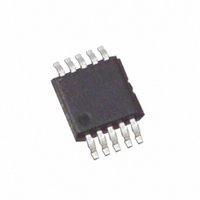
ISL95710WIU10Z Intersil, ISL95710WIU10Z Datasheet - Page 4

ISL95710WIU10Z
Manufacturer Part Number
ISL95710WIU10Z
Description
IC XDCP 128-TAP 10KOHM 10-MSOP
Manufacturer
Intersil
Series
XDCP™r
Datasheet
1.ISL95710WIU10Z-T.pdf
(10 pages)
Specifications of ISL95710WIU10Z
Taps
128
Resistance (ohms)
10K
Number Of Circuits
1
Temperature Coefficient
50 ppm/°C Typical
Memory Type
Non-Volatile
Interface
Up/Down (3-Wire)
Voltage - Supply
2.7 V ~ 5.5 V
Operating Temperature
-40°C ~ 85°C
Mounting Type
Surface Mount
Package / Case
10-MSOP, Micro10™, 10-uMAX, 10-uSOP
Resistance In Ohms
10K
Number Of Elements
1
# Of Taps
128
Resistance (max)
10KOhm
Interface Type
Serial (3-Wire)
Single Supply Voltage (typ)
-3.3V
Dual Supply Voltage (typ)
Not RequiredV
Single Supply Voltage (min)
-2.7V
Single Supply Voltage (max)
-5.5V
Dual Supply Voltage (min)
Not RequiredV
Dual Supply Voltage (max)
Not RequiredV
Operating Temp Range
-40C to 85C
Operating Temperature Classification
Industrial
Mounting
Surface Mount
Pin Count
10
Lead Free Status / RoHS Status
Lead free / RoHS Compliant
Operating Specifications
AC Electrical Specifications
EEPROM SPECS
3-WIRE INTERFACE SPECS
Hysteresis
SYMBOL
(Note 13)
V- Ramp
I
I
I
LkgDig
I
CCSB
IL_CS
I
I
Vpor
Cpin
V-SB
I
I
V
CC1
CC2
V
SYMBOL
V-1
V-2
(Note 14)
IH
t
IL
CPHNS
t
CPHS
t
t
t
t
t
t
Cl
lD
DI
lH
lC
lL
V
V- supply current, volatile write/read
V
V- supply current, nonvolatile write
V
V- current (standby)
Leakage current, at pins INC, CS, and
U/D
Leakage at CS, input low
Power-on recall for both V- and V
V- ramp rate
EEPROM Endurance
EEPROM Retention
INC, CS, and U/D input buffer LOW
voltage
INC, CS, and U/D input buffer HIGH
voltage
INC, CS, and U/D input buffer
hysteresis
INC, CS, and U/D pin capacitance
CC
CC
CC
supply current, volatile write/read CS = V
supply current, nonvolatile write
current (standby)
CS to INC setup
INC HIGH to U/D change
U/D to INC setup
INC LOW period
INC HIGH period
INC inactive to CS inactive
CS deselect time (STORE)
CS deselect time (NO STORE)
PARAMETER
4
Over the recommended operating conditions unless otherwise specified.
V
PARAMETER
CC
= 5V ±10%, T
CC
R
CS = V
R
U/D = V
from V
U/D = V
from V
V
V
V- = -5.5V, CS = V
V- = -3.6V, CS = V
V
V
V-
V
Temperature ≤ +75°C
CC
CC
IL
IL
CC
L
L
, R
, R
or V
= 0V
A
= +5.5V, I
= +3.6V, I
H
H
= Full Operating Temperature Range unless otherwise stated
IL
IL
IL
, R
IL
, R
IL
IL
IH
, U/D = V
, U/D = V
to V
to V
W
W
or V
or V
ISL95710
applied at pin
not connected
not connected
IH
IH
TEST CONDITIONS
IH
IH
2
2
. R
. R
C Interface in Standby State
C Interface in Standby State
and INC = V
and INC = V
IL
IL
L
L
IH
IH
, R
, R
or V
or V
H
H
, R
, R
IH
IH
W
W
MIN
and INC = V
and INC = V
100
100
20
1
1
1
1
1
not connected
not connected
IH
IH
, CS = transitions
, CS = transitions
IL
IL
TYP (Note 1)
or V
or V
IH
IH
,
,
0.7*V
200,000
-100
-300
MIN
-2.5
-0.3
-10
50
-3
-5
-2
CC
(Note 1)
MAX
0.15*
TYP
V
10
CC
0.3*V
V
MAX
500
500
-0.2
2.5
0.3
CC
10
1
1
CC
+
August 31, 2006
UNIT
ms
ns
ns
µs
µs
µs
µs
µs
Cycles
Years
UNIT
V/ms
FN8240.3
mA
µA
µA
µA
µA
µA
µA
µA
µA
µA
pF
V
V
V
V
V


