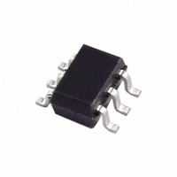
AD5246BKS5-R2 Analog Devices Inc, AD5246BKS5-R2 Datasheet

AD5246BKS5-R2
Specifications of AD5246BKS5-R2
Available stocks
Related parts for AD5246BKS5-R2
AD5246BKS5-R2 Summary of contents
Page 1
FEATURES 128-position End-to-end resistance 5 kΩ, 10 kΩ, 50 kΩ, 100 kΩ Ultracompact SC70 × 2.1 mm) package 2 I C® compatible interface Full read/write of wiper register Power-on preset to midscale Single supply 2 5.5 ...
Page 2
AD5246 TABLE OF CONTENTS Specifications ..................................................................................... 3 Electrical Characteristics—5 kΩ Version .................................. 3 Electrical Characteristics—10 kΩ, 50 kΩ, 100 kΩ Versions .. 4 Timing Characteristics ................................................................ 5 Absolute Maximum Ratings ............................................................ 6 Pin Configuration and Function Descriptions ............................. 7 Typical ...
Page 3
SPECIFICATIONS ELECTRICAL CHARACTERISTICS—5 kΩ VERSION ± 10 ± 10 Table 1. Parameter DC CHARACTERISTICS—RHEOSTAT MODE 2 Resistor Differential Nonlinearity 2 Resistor Integral Nonlinearity 3 Nominal Resistor Tolerance Resistance ...
Page 4
AD5246 ELECTRICAL CHARACTERISTICS—10 kΩ, 50 kΩ, 100 kΩ VERSIONS ± 10 ± 10 Table 2. Parameter DC CHARACTERISTICS, RHEOSTAT MODE 2 Resistor Differential Nonlinearity 2 Resistor Integral ...
Page 5
TIMING CHARACTERISTICS ± 10 ± 10 Table 3. Parameter INTERFACE TIMING CHARACTERISTICS SCL Clock Frequency t Bus Free Time Between STOP and START BUF ...
Page 6
AD5246 ABSOLUTE MAXIMUM RATINGS T = 25°C, unless otherwise noted. A Table 4. Parameter V to GND GND A W Terminal Current, A–B, A–W, B–W Pulsed 1 Continuous Digital Inputs and Output Voltage to GND ...
Page 7
PIN CONFIGURATION AND FUNCTION DESCRIPTIONS Table 5. Pin Function Descriptions Pin No. Mnemonic GND 3 SCL 4 SDA AD5246 GND W 2 TOP VIEW 5 (Not to ...
Page 8
AD5246 TYPICAL PERFORMANCE CHARACTERISTICS 1.0 0.8 0 2.7V DD 0.4 0 5.5V DD –0.2 –0.4 –0.6 –0.8 –1 CODE (Decimal) Figure 3. R-INL vs. Code vs. Supply Voltages 0.5 0.4 ...
Page 9
DIGITAL INPUTS = 0V CODE = 0x40 5. 0.1 0.01 –40 –25 – TEMPERATURE (° C) Figure 9. Supply Current vs. Temperature 500 400 300 = ...
Page 10
AD5246 0 –6 –12 –18 100kΩ –24 –30 –36 –42 –48 –54 –60 1k 10k 100k FREQUENCY (Hz) Figure 15. –3 dB Bandwidth @ Code = 0x80 0. 5.5V DD CODE = 0x55 0. ...
Page 11
TEST CIRCUITS Figure 21 Figure 25 to define the test conditions used in the product Specification tables. DUT Figure 21. Test Circuit for Resistor Position Nonlinearity Error (Rheostat Operation; R-INL, R-DNL DUT ...
Page 12
AD5246 INTERFACE Table 6. Write Mode Slave Address Byte Table 7. Read Mode Slave Address Byte S = Start Condition Stop Condition. A ...
Page 13
OPERATION The AD5246 is a 128-position, digitally controlled variable resistor (VR) device. PROGRAMMING THE VARIABLE RESISTOR Rheostat Operation The nominal resistance of the RDAC between Terminal A and Terminal B is available in 5 kΩ, 10 kΩ, 50 kΩ, and ...
Page 14
AD5246 A repeated write function gives the user flexibility to update the RDAC output a number of times after addressing the part only once. For example, after the RDAC has acknowledged its slave address in write mode, the RDAC output ...
Page 15
LAYOUT AND POWER SUPPLY BYPASSING good practice to use a compact, minimum lead-length layout design. The leads to the inputs should be as direct as possible with a minimum conductor length. Ground paths should have low resistance ...
Page 16
AD5246 OUTLINE DIMENSIONS 0.10 MAX COPLANARITY 0.10 ORDERING GUIDE Model R (kΩ AD5246BKSZ5-RL7 5 1 AD5246BKSZ10- AD5246BKSZ10-RL7 10 1 AD5246BKSZ50-RL7 50 1 AD5246BKSZ100-R2 100 1 AD5246BKSZ100-RL7 100 EVAL-AD5246EBZ RoHS Compliant Part. 2 ...


