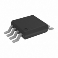
AD5310BRMZ Analog Devices Inc, AD5310BRMZ Datasheet - Page 2

AD5310BRMZ
Manufacturer Part Number
AD5310BRMZ
Description
IC DAC 10BIT R-R W/BUFF 8-MSOP
Manufacturer
Analog Devices Inc
Datasheet
1.AD5310BRMZ.pdf
(12 pages)
Specifications of AD5310BRMZ
Data Interface
Serial
Settling Time
6µs
Number Of Bits
10
Number Of Converters
1
Voltage Supply Source
Single Supply
Power Dissipation (max)
1.25mW
Operating Temperature
-40°C ~ 105°C
Mounting Type
Surface Mount
Package / Case
8-MSOP, Micro8™, 8-uMAX, 8-uSOP,
Resolution (bits)
10bit
Sampling Rate
167kSPS
Input Channel Type
Serial
Supply Voltage Range - Analog
2.7V To 5.5V
Supply Current
140µA
Digital Ic Case Style
SOP
Package
8MSOP
Resolution
10 Bit
Conversion Rate
167 KSPS
Architecture
Resistor-String
Digital Interface Type
Serial (3-Wire, SPI, QSPI, Microwire)
Number Of Outputs Per Chip
1
Output Type
Voltage
Full Scale Error
-1.25 %FSR
Integral Nonlinearity Error
±4 LSB
Maximum Settling Time
8 us
Lead Free Status / RoHS Status
Lead free / RoHS Compliant
Lead Free Status / RoHS Status
Lead free / RoHS Compliant, Lead free / RoHS Compliant
Available stocks
Company
Part Number
Manufacturer
Quantity
Price
Part Number:
AD5310BRMZ
Manufacturer:
ADI/亚德诺
Quantity:
20 000
Company:
Part Number:
AD5310BRMZ-REEL7
Manufacturer:
ROHM
Quantity:
52
AD5310–SPECIFICATIONS
Parameter
STATIC PERFORMANCE
OUTPUT CHARACTERISTICS
LOGIC INPUTS
POWER REQUIREMENTS
NOTES
1
2
3
Specifications subject to change without notice.
Temperature ranges are as follows: B Version: –40 C to +105 C.
Linearity calculated using a reduced code range of 12 to 1011. Output unloaded.
Guaranteed by design and characterization, not production tested.
Resolution
Relative Accuracy
Differential Nonlinearity
Zero Code Error
Full-Scale Error
Gain Error
Zero Code Error Drift
Gain Temperature Coefficient
Output Voltage Range
Output Voltage Settling Time
Slew Rate
Capacitive Load Stability
Digital-to-Analog Glitch Impulse
Digital Feedthrough
DC Output Impedance
Short Circuit Current
Power-Up Time
Input Current
V
V
V
V
Pin Capacitance
V
I
I
Power Efficiency
DD
DD
INL
INL
INH
INH
DD
V
V
V
V
I
OUT
DD
DD
(All Power-Down Modes)
DD
DD
, Input Low Voltage
, Input Low Voltage
(Normal Mode)
, Input High Voltage
, Input High Voltage
= +4.5 V to +5.5 V
= +2.7 V to +3.6 V
/I
= +4.5 V to +5.5 V
= +2.7 V to +3.6 V
DD
3
2
3
Min
10
0
2.4
2.1
2.7
B Version
Typ
+5
–0.15 –1.25
–20
–5
6
1
470
1000
20
0.5
1
50
20
2.5
5
140
115
0.2
0.05
93
(V
T
MIN
DD
1
to T
= +2.7 V to +5.5 V; R
Max
+40
V
8
0.8
0.6
3
5.5
250
200
1
1
4
0.5
1.25
1
DD
MAX
unless otherwise noted)
–2–
Units
Bits
LSB
LSB
mV
% of FSR
% of FSR
ppm of FSR/ C
V
V/ s
pF
pF
nV-s
nV-s
mA
mA
V
V
V
V
pF
V
%
V/ C
s
s
s
A
A
A
A
A
L
= 2 k
Conditions/Comments
See Figure 2.
Guaranteed Monotonic by Design. See Figure 3.
All Zeroes Loaded to DAC Register. See Figure 6.
All Ones Loaded to DAC Register. See Figure 6.
1/4 Scale to 3/4 Scale Change (100 Hex to 300 Hex).
R
R
R
1 LSB Change Around Major Carry. See Figure 19.
V
V
Coming Out of Power-Down Mode. V
Coming Out of Power-Down Mode. V
V
V
V
V
DAC Active and Excluding Load Current
V
V
V
V
I
LOAD
L
L
L
DD
DD
DD
DD
DD
DD
IH
IH
IH
IH
to GND; C
= 2 k ; 0 pF < C
=
= 2 k
= V
= V
= V
= V
= +5 V
= +3 V
= +5 V
= +3 V
= +5 V
= +3 V
= 2 mA. V
DD
DD
DD
DD
and V
and V
and V
and V
L
= 500 pF to GND; all specifications
IL
IL
IL
IL
DD
= GND
= GND
= GND
= GND
L
= +5 V
< 500 pF. See Figure 16.
DD
DD
= +5 V
= +3 V
REV. A


