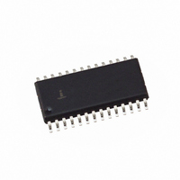
HI5741BIB Intersil, HI5741BIB Datasheet - Page 12

HI5741BIB
Manufacturer Part Number
HI5741BIB
Description
IC DAC 14-BIT 100MSPS 28-SOIC
Manufacturer
Intersil
Datasheet
1.HI5741BIB.pdf
(13 pages)
Specifications of HI5741BIB
Settling Time
20ns
Number Of Bits
14
Data Interface
Parallel
Number Of Converters
1
Voltage Supply Source
Analog and Digital, Dual ±
Power Dissipation (max)
650mW
Operating Temperature
-40°C ~ 85°C
Mounting Type
Surface Mount
Package / Case
28-SOIC (7.5mm Width)
Lead Free Status / RoHS Status
Contains lead / RoHS non-compliant
Available stocks
Company
Part Number
Manufacturer
Quantity
Price
Company:
Part Number:
HI5741BIB
Manufacturer:
HARRIS
Quantity:
91
Part Number:
HI5741BIB
Manufacturer:
INTERSIL
Quantity:
20 000
Company:
Part Number:
HI5741BIBZ
Manufacturer:
Intersil
Quantity:
126
Signal to Noise Ratio (SNR) is the ratio of a fundamental to
the noise floor of the analog output. The first 5 harmonics
are ignored, and an output filter of
used to eliminate alias products.
Total Harmonic Distortion (THD) is the ratio of the DAC
output fundamental to the RMS sum of the harmonics. The
first 5 harmonics are included, and an output filter of
clock frequency is used to eliminate alias products.
Spurious Free Dynamic Range (SFDR) is the amplitude
difference from a fundamental to the largest harmonically or
non-harmonically related spur. A sine wave is loaded into
the D/A and the output filtered at
eliminate noise from clocking alias terms.
BASEBAND
STREAM
BIT
CONTROLLER
ENCODER
FIGURE 27. PSK MODULATOR USING THE HI5741 AND HSP45106 16-BIT NCO
12
33 MSPS
1
/
1
2
/
2
CLK
the clock frequency to
the clock frequency is
V
V
V
CC
CC
CC
C11
B11
C10
A11
H11
G11
G10
D10
K11
B10
A10
E11
H10
F10
F11
J11
J10
G9
K9
B8
A8
B6
B7
A7
C7
C6
A6
A5
C5
A4
B4
A3
A2
B3
A1
B9
F9
E9
K2
J2
MOD2
MOD1
MOD0
PMSEL
ENPOREG
ENOFREG
ENCFREG
ENPHAC
ENTIREG
INHOFR
INITPAC
INITTAC
TEST
PARSER
BINFMT
C15_MSB
C4
C13
C12
C11
C10
C9
C8
C7
C6
C5
C4
C3
C2
C1
C0
A2
A1
A0
CS
WR
PACI
OES
OEC
U2
CLK
HSP45106
1
/
2
DACSTRB
the
COS15
COS14
COS13
COS12
COS11
COS10
SIN15
SIN14
SIN13
SIN12
SIN11
SIN10
COS9
COS8
COS7
COS6
COS5
COS4
COS3
COS2
COS1
COS0
TICO
SIN9
SIN8
SIN7
SIN6
SIN5
SIN4
SIN3
SIN2
SIN1
SIN0
HI5741
L1
K3
L2
L3
L4
J5
K5
L5
K6
J6
J7
L7
L6
L8
K8
L9
L10
C2
B1
C1
D1
E3
E2
E1
F2
F3
G3
G1
G2
H1
H2
J1
K1
B2
Multi-Tone Power Ratio (MTPR) is the amplitude difference
from peak amplitude to peak distortion (either harmonic or
non-harmonic). An 8 tone pattern is loaded into the D/A. The
tone spacing of this pattern (∆f) is created such that tones 1
through 4 and 5 through 8 are spaced equally, with tones 4
and 5 spaced at 2∆f. MTPR is measured as the dynamic
range from peak power to peak distortion in the 2∆f gap.
Intermodulation Distortion (IMD) is the measure of the
sum and difference products produced when a two tone
input is driven into the D/A. The distortion products created
will arise at sum and difference frequencies of the two tones.
IMD can be calculated using the following equation:
IMD
-5.2V_D
R
50
V
4
CC
=
-5.2V_D
20Log (RMS of Sum and Difference Distortion Products)
------------------------------------------------------------------------------------------------------------------------------------------------------ -
16
10
15
28
17
18
11
12
13
14
1
2
3
4
5
6
7
8
9
DV
D13 (MSB)
D12
D11
D10
D9
D8
D7
D6
D5
D4
D3
D2
D1
D0 (LSB)
DGND
DGND
DV
U1
CLK
EE
CC
C AMP OUT
HI5741
10µH
10µH
(
C AMP IN
REF OUT
L
RMS Amplitude of the Fundamental
L
1
2
ARET
AV
AV
I
R
I
OUT
OUT
SET
SS
EE
-5.2V_A
/
21
20
24
25
26
23
19
27
22
-5.2V_A
C
C
FILTER
2
1
976
R
64
R
64
R
1
2
3
0.1µF
0.01µF
TO RF
UP-CONVERT
STAGE
-5.2V_A
-5.2V_A
September 20, 2006
)
FN4071.12


