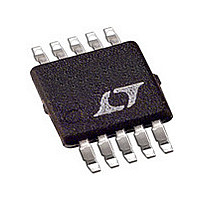
LTC4212CMSTR Linear Technology, LTC4212CMSTR Datasheet - Page 18

LTC4212CMSTR
Manufacturer Part Number
LTC4212CMSTR
Description
Manufacturer
Linear Technology
Datasheet
1.LTC4212CMSTR.pdf
(24 pages)
Specifications of LTC4212CMSTR
Linear Misc Type
Positive Low Voltage
Family Name
LTC4212
Package Type
MSOP
Operating Supply Voltage (min)
2.5V
Operating Supply Voltage (max)
16.5V
Operating Temperature (min)
0C
Operating Temperature (max)
70C
Operating Temperature Classification
Commercial
Product Depth (mm)
3mm
Product Height (mm)
0.86mm
Product Length (mm)
3mm
Mounting
Surface Mount
Pin Count
10
Lead Free Status / Rohs Status
Not Compliant
OPERATIO
LTC4212
It consists of the time the FAULT pin takes to discharge
C
circuit breaker (Time Points 9 to 11), the time it takes the
pull-up resistor at the ON pin to charge C
1.316V (Time Points 11 to 12) and the elapsed time before
the external N-channel starts to conduct during the second
timing cycle (Time Points 12 to 16).
18
AUTO
V
CONVERTER
CC
– V
OUTPUT
TIMER
DC/DC
FAULT
(Time Points 9 to 10), the 120 s needed to reset the
SENSE
GATE
PGT
PGF
V
PGI
ON
CC
1
2.34V
V
CC
U
2
3
Figure 4. Power-Up with Overcurrent, Slow Comparator Trips the Circuit Breaker
CYCLE (C
1ST TIMING
TIMER
V
REF
)
4
5 6
V
AUTO
CC
SOFT-START
– V
CYCLE (C
2ND TIMING
ACTIVE
SENSE
above
7
TIMER
= 50mV
V
0.95V
0.65V
REF
)
POWER GOOD TIMER
8
> 50mV, >18 s
ENABLED (C
Sense Resistor Considerations
The fault current level at which the LTC4212’s internal
electronic circuit breaker trips is determined by a sense
resistor connected between the LTC4212’s V
pins and two separate trip points. The first trip point is set
9
PGT
)
10 11
12
13
1415
CYCLE (C
1ST TIMING
CC
and SENSE
V
TIMER
REF
)
4212 F04
4212f
16


