KMI18/4,115 NXP Semiconductors, KMI18/4,115 Datasheet - Page 5
KMI18/4,115
Manufacturer Part Number
KMI18/4,115
Description
Manufacturer
NXP Semiconductors
Datasheet
1.KMI184115.pdf
(12 pages)
Specifications of KMI18/4,115
Lead Free Status / Rohs Status
Supplier Unconfirmed


Philips Semiconductors
Notes
1. LOW: open collector output transistor open (V
2. HIGH: open collector output transistor closed (V
3. Measured with harmonic magnetic field in ‘y’ with H
4. Higher magnetic fields could cause irreversible shifts of parameters.
5. Output pins are designed for electrostatic sensitivity with field strengths up to 2 kV according to Human Body
6. MR pins are designed for electrostatic sensitivity with field strengths up to 0.3 kV according to Human Body
7. Measured with harmonic magnetic field in ‘y’ with H
2000 Sep 05
t
d
Environmental conditions
Capacity of sensor shield
C
dfOUT
tdfOUT
s
Integrated rotational speed sensor
Model (HBM), MIL-STD-883, Method 3015.
Model (HBM), MIL-STD-883, Method 3015.
SYMBOL
output signal delay time of
HL-edge
jitter of HL-edge
external magnetic
influence
ESD protection of sensor
pins V
ESD protection of internal
pins B1, B2, B3 and B4
EMC: Compliance to
ISO 11452-5
interference for pulse:
ISO 7637; pulse 4
shield capacity
CC
PARAMETER
, OUT and GND
T
normalized to cycle of one
reference mark; note 3
note 4
compliance to
IEC 0801-2 (IV); note 5
compliance to
IEC 0801-2 (IV); note 6
(A, stripline, 300 V/m,
10 kHz to 400 MHz,
1500 mm); note 7
T = 25 C; note 7
B1 versus B2 of
MR bridge; f = 1 MHz;
U
amb
osc
OUT
OUT
= 200 mV
= ( 40 to +150) C
CONDITIONS
< 1 V).
y max
y max
> 4 V).
5
= 1 kA/m and f
= 1 kA/m and f
m
m
1.95
1.5
0
2
0.3
function A
37
= 10, 1000 and 8000 Hz.
= 50 Hz.
MIN.
2.3
43
TYP.
Objective specification
2.55
3.5
0.15
30
48
MAX.
KMI18/4
%
kA/m
kV
kV
pF
s
s
UNIT
Related parts for KMI18/4,115
Image
Part Number
Description
Manufacturer
Datasheet
Request
R

Part Number:
Description:
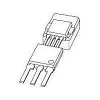
Speed Sensors SNSR MAGNETIC TAPE-7
Manufacturer:
NXP Semiconductors

Part Number:
Description:
SPEED SENSOR ROTATIONAL SOT477A
Manufacturer:
NXP Semiconductors
Datasheet:
Part Number:
Description:
NXP Semiconductors designed the LPC2420/2460 microcontroller around a 16-bit/32-bitARM7TDMI-S CPU core with real-time debug interfaces that include both JTAG andembedded trace
Manufacturer:
NXP Semiconductors
Datasheet:

Part Number:
Description:
NXP Semiconductors designed the LPC2458 microcontroller around a 16-bit/32-bitARM7TDMI-S CPU core with real-time debug interfaces that include both JTAG andembedded trace
Manufacturer:
NXP Semiconductors
Datasheet:
Part Number:
Description:
NXP Semiconductors designed the LPC2468 microcontroller around a 16-bit/32-bitARM7TDMI-S CPU core with real-time debug interfaces that include both JTAG andembedded trace
Manufacturer:
NXP Semiconductors
Datasheet:
Part Number:
Description:
NXP Semiconductors designed the LPC2470 microcontroller, powered by theARM7TDMI-S core, to be a highly integrated microcontroller for a wide range ofapplications that require advanced communications and high quality graphic displays
Manufacturer:
NXP Semiconductors
Datasheet:
Part Number:
Description:
NXP Semiconductors designed the LPC2478 microcontroller, powered by theARM7TDMI-S core, to be a highly integrated microcontroller for a wide range ofapplications that require advanced communications and high quality graphic displays
Manufacturer:
NXP Semiconductors
Datasheet:
Part Number:
Description:
The Philips Semiconductors XA (eXtended Architecture) family of 16-bit single-chip microcontrollers is powerful enough to easily handle the requirements of high performance embedded applications, yet inexpensive enough to compete in the market for hi
Manufacturer:
NXP Semiconductors
Datasheet:
Part Number:
Description:
The XA-S3 device is a member of Philips Semiconductors? XA(eXtended Architecture) family of high performance 16-bitsingle-chip microcontrollers
Manufacturer:
NXP Semiconductors
Datasheet:

Part Number:
Description:
The NXP BlueStreak LH75401/LH75411 family consists of two low-cost 16/32-bit System-on-Chip (SoC) devices
Manufacturer:
NXP Semiconductors
Datasheet:
Part Number:
Description:
The NXP LPC3130/3131 combine an 180 MHz ARM926EJ-S CPU core, high-speed USB2
Manufacturer:
NXP Semiconductors
Datasheet:
Part Number:
Description:
The NXP LPC3141 combine a 270 MHz ARM926EJ-S CPU core, High-speed USB 2
Manufacturer:
NXP Semiconductors
Part Number:
Description:
The NXP LPC3143 combine a 270 MHz ARM926EJ-S CPU core, High-speed USB 2
Manufacturer:
NXP Semiconductors

Part Number:
Description:
The NXP LPC3152 combines an 180 MHz ARM926EJ-S CPU core, High-speed USB 2
Manufacturer:
NXP Semiconductors