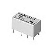
9-1393792-7 TE Connectivity, 9-1393792-7 Datasheet - Page 94

9-1393792-7
Manufacturer Part Number
9-1393792-7
Description
Electromechanical Relay DPDT 3A 12VDC 720Ohm Through Hole
Manufacturer
TE Connectivity
Type
Signal Relayr
Specifications of 9-1393792-7
Contact Arrangement
DPDT
Dc Coil Voltage
12 V
Coil Current
16.67 mA
Mounting
Through Hole
Relay Construction
Non-Latching
Coil Voltage Dc
12V
Contact Form
2 Form C
Voltage Rating (vdc)
220V
Voltage Rating (vac)
250V
Dropout Volt (min)
0.6VDCV
Coil Resistance
720Ohm
Pick-up Voltage (max)
8.4VDC
Maximum Power Rating
60W/125VA
Operate Time
5ms
Contact Current Rating
3A
Contact Material
AgNi/Au
Coil Suppression Diode
No
Push To Test Button
No
Led Indicator
No
Seal
Unsealed
Product Height (mm)
11mm
Product Depth (mm)
10mm
Product Length (mm)
20.2mm
Operating Temp Range
-25C to 85C
Pin Count
8
Mounting Style
Through Hole
Termination Style
PC Pin
Package / Case
DIP
Lead Free Status / Rohs Status
Compliant
- Current page: 94 of 484
- Download datasheet (15Mb)
322
U
U
The operating voltage limits U
the temperature according to the formula:
U
and
U
t
U
U
k
Our authorized distributors are more likely to stock the following items for immediate delivery.
None at present.
Outline Dimensions
PC Board Layout (Bottom View)
THT Version
Recommended Soldering Conditions
Vapor Phase Soldering: Temperature/Time Profile
(Lead Temperature)
Ordering Information
See "Part Number" column in Coil Data chart on previous page for available
base part numbers in the IM series.
For THT versions, add the suffix "TS" to the base part number.
For gull-wing SMT versions, add the suffix "GR" to the base part number.
For J-leg SMT versions, add the suffix "JR" to the base part number.
THT Version
Dimensions are shown for
reference purposes only.
amb
.018
I
(.46
I
II
I tamb
II tamb
I tamb
II tamb
, k
=
=
II
=
.006
.15
=
.222
(5.65
)
external preheating
.125
(3.2)
D1=
D2=
– .008
– .2
Minimum voltage at 23 C after pre-energizing
with nominal voltage without contact current
Maximum continous voltage at 23
K
K
= Ambient temperature
= Minimum voltage at ambient temperature, t
= Maximum voltage at ambient temperature, t
= Factors (dependent on temperature), see diagram
.126
(3.2)
100 C
I
Il
130 C
215 C
180 C
.087
.047
)
.126
(1.2
(2.2
· U
(3.2
· U
I 23 C
(2.2)
Il 23 C
.087
.15
D1
.15
.006
.006
.15
.006
.393
(10
(2.2)
)
)
)
.087
D2 D2
.08
.003
)
.030 (.75) DIA.
(5.08
I
.2
and U
MIN.
.015
.006
(.4)
.15
Time (s)
II
)
20-40 sec
depend on
.236
(5.08
.2
(6
Solid Line: Typical
Dotted Line: Process Limits
.004
.08
Dimensions are in inches over
(millimeters) unless otherwise
specified.
.003
Solder Pad Layout (Bottom Views)
.047
SMT Version w/ Gull Wings
(1.2
.1
)
)
(according to CECC 00802)
.006
.15
.236
(6)
)
.126
(3.2)
amb
amb
forced
cooling
SMT Version w/ Gull Wings
.222
(5.65
.087
(2.2)
D1=
D2=
– .008
(2.2)
.087
– .2
.087
.126
(3.2
(2.2
)
Catalog 1308242
.15
.006
.15
.028
.006
.157
D1
(4)
(.7
.393
Issued 3-03
)
(10
)
.315
.1
D2 D2
.015
.004
(.4)
(8)
)
.08
.003
)
Packaging Information
THT IM series relays are shipped in tubes of 50. There are 1,000 relays in
a full carton. SMT IM series relays are shipped in reels of 1,000. There
are 1,000 or 5,000 relays in a full carton.
Infrared Soldering: Temperature/Time Profile
(Lead Temperature)
.047
(1.2
SMT Version w/ J Legs
.173
(4.4)
Specifications and availability
subject to change.
.006
.15
)
.236
(5.08
.295
(6
.2
(7.5
.08
.004
.003
.011
.3
.1
)
(3.2)
.126
)
)
.087
(2.2)
(2.2)
.087
Ambient temperature t
SMT Version w/ J Legs
max. 245 C
.222
(5.65
.028
D1=
D2=
(.7
.094
(2.4)
– .008
130 C
– .2
180 C
215 C
.087
.126
(3.2
(2.2
.1
.004
Time (s)
)
)
.252
(6.4)
.15
.006
.15
.006
D1
Solid Line: Typical
Dotted Line: Process Limits
)
)
.393
(10
D2 D2
.015
(.4)
.08
Wiring Diagram
(Bottom View)
.003
)
10 sec
ca. 40 sec
amb
www.tycoelectronics.com
Technical support:
Refer to inside back cover.
[ C]
T1=
T2=
.236
AXICOM
(6
.110
(5.08
(2.8
.2
T1
T2
.08
.003
.004
)
.007
.2
.1
)
)
Related parts for 9-1393792-7
Image
Part Number
Description
Manufacturer
Datasheet
Request
R

Part Number:
Description:
CRIMP, RECEPTACLE
Manufacturer:
TE Connectivity
Datasheet:

Part Number:
Description:
PIGGYBACK DISCONNECT, 6.35MM, CRIMP BLUE
Manufacturer:
TE Connectivity
Datasheet:

Part Number:
Description:
Manufacturer:
TE Connectivity
Datasheet:

Part Number:
Description:
CRIMP TERMINAL, FEMALE, BLUE
Manufacturer:
TE Connectivity
Datasheet:

Part Number:
Description:
Manufacturer:
TE Connectivity
Datasheet:

Part Number:
Description:
CONN HEADR BRKWAY .100 13POS R/A
Manufacturer:
Tyco Electronics
Datasheet:

Part Number:
Description:
CONN HEADR BRKWAY .100 13POS R/A
Manufacturer:
Tyco Electronics
Datasheet:

Part Number:
Description:
CONN HDR BRKWAY .100 13POS VERT
Manufacturer:
Tyco Electronics
Datasheet:

Part Number:
Description:
CONN HDR BRKWAY .100 13POS VERT
Manufacturer:
Tyco Electronics
Datasheet:

Part Number:
Description:
CONN HDR BRKWAY .100 13POS VERT
Manufacturer:
Tyco Electronics
Datasheet:

Part Number:
Description:
CONN HEADR BRKWAY .100 13POS R/A
Manufacturer:
Tyco Electronics
Datasheet:

Part Number:
Description:
CONN HEADR BRKWAY .100 13POS STR
Manufacturer:
Tyco Electronics
Datasheet:

Part Number:
Description:
CONN HEADR BRKWAY .100 13POS STR
Manufacturer:
Tyco Electronics
Datasheet:

Part Number:
Description:
CONN HEADR BRKWAY .100 13POS STR
Manufacturer:
Tyco Electronics
Datasheet:

Part Number:
Description:
CONN HEADR BRKWAY .100 13POS R/A
Manufacturer:
Tyco Electronics
Datasheet:


