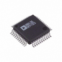
AD7835AS Analog Devices Inc, AD7835AS Datasheet - Page 7

AD7835AS
Manufacturer Part Number
AD7835AS
Description
IC DAC 14BIT QUAD PARA 44-MQFP
Manufacturer
Analog Devices Inc
Datasheet
1.AD7835ASZ.pdf
(28 pages)
Specifications of AD7835AS
Rohs Status
RoHS non-compliant
Settling Time
10µs
Number Of Bits
14
Data Interface
Parallel
Number Of Converters
4
Voltage Supply Source
Analog and Digital, Dual ±
Power Dissipation (max)
465mW
Operating Temperature
-40°C ~ 85°C
Mounting Type
Surface Mount
Package / Case
44-MQFP, 44-PQFP
Available stocks
Company
Part Number
Manufacturer
Quantity
Price
Company:
Part Number:
AD7835AS
Manufacturer:
AD
Quantity:
13 888
Company:
Part Number:
AD7835ASZ
Manufacturer:
OKI
Quantity:
490
Company:
Part Number:
AD7835ASZ
Manufacturer:
ADI
Quantity:
850
Company:
Part Number:
AD7835ASZ
Manufacturer:
Analog Devices Inc
Quantity:
10 000
Part Number:
AD7835ASZ
Manufacturer:
ADI/亚德诺
Quantity:
20 000
Company:
Part Number:
AD7835ASZ-REEL
Manufacturer:
Analog Devices Inc
Quantity:
10 000
ABSOLUTE MAXIMUM RATINGS
T
0.3 V. If it is possible for this to happen during power supply sequencing, the diode protection scheme shown in Figure 5 can be used to
provide protection.
Table 5.
Parameter
V
V
V
AGND to DGND
Digital Inputs to DGND
V
V
V
DSG to AGND
V
Operating Temperature Range, T
Storage Temperature Range
Junction Temperature, T
Power Dissipation, P
Lead Temperature
Stresses above those listed under Absolute Maximum Ratings
may cause permanent damage to the device. This is a stress
rating only; functional operation of the device at these or any
other conditions above those indicated in the operational
section of this specification is not implied. Exposure to absolute
maximum rating conditions for extended periods may affect
device reliability.
CC
DD
SS
REF
REF
REF
OUT
A
Industrial (A Version)
Soldering
= 25°C unless otherwise noted. Transient currents of up to 100 mA do not cause SCR latch-up. V
to AGND
to DGND
(+) to V
(+) to AGND
(–) to AGND
to AGND
(1–4) to AGND
REF
(–)
D
(max)
J
(max)
A
Rating
−0.3 V to +7 V, or V
(whichever is lower)
−0.3 V to +17 V
+0.3 V to –17 V
−0.3 V to +0.3 V
−0.3 V to V
−0.3 V to +18 V
V
V
V
V
−40°C to +85°C
−65°C to +150°C
150°C
(T
JEDEC Industry Standard
J-STD-020
SS
SS
SS
SS
J
− T
– 0.3 V to V
– 0.3 V to V
– 0.3 V to V
– 0.3 V to V
A
)/θ
JA
CC
+ 0.3 V
DD
DD
DD
DD
+ 0.3 V
+ 0.3 V
+ 0.3 V
+ 0.3 V
DD
+ 0.3 V
Rev. D | Page 7 of 28
THERMAL RESISTANCE
θ
soldered in a circuit board for surface-mount packages.
Table 6. Thermal Resistance
Package Type
PDIP
SOIC
MQFP
PLCC
ESD CAUTION
JA
is specified for the worst-case conditions, that is, a device
Figure 5. Diode Protection
V
V
CC
AD7834/
DD
DD
AD7835
IN4148
must not exceed V
SD103C
V
V
CC
CC
θ
75
75
95
55
AD7834/AD7835
JA
DD
by more than
Unit
°C/W
°C/W
°C/W
°C/W


