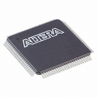
EPM570T100C3N Altera, EPM570T100C3N Datasheet - Page 68

EPM570T100C3N
Manufacturer Part Number
EPM570T100C3N
Description
IC MAX II CPLD 570 LE 100-TQFP
Manufacturer
Altera
Series
MAX® IIr
Specifications of EPM570T100C3N
Programmable Type
In System Programmable
Delay Time Tpd(1) Max
5.4ns
Voltage Supply - Internal
2.5V, 3.3V
Number Of Logic Elements/blocks
570
Number Of Macrocells
440
Number Of I /o
76
Operating Temperature
0°C ~ 85°C
Mounting Type
Surface Mount
Package / Case
100-TQFP, 100-VQFP
Voltage
2.5V, 3.3V
Memory Type
FLASH
Number Of Logic Elements/cells
570
Family Name
MAX II
# Macrocells
440
Frequency (max)
3.01205GHz
Propagation Delay Time
5.4ns
Number Of Logic Blocks/elements
57
# I/os (max)
76
Operating Supply Voltage (typ)
2.5/3.3V
In System Programmable
Yes
Operating Supply Voltage (min)
2.375V
Operating Supply Voltage (max)
3.6V
Operating Temp Range
0C to 85C
Operating Temperature Classification
Commercial
Mounting
Surface Mount
Pin Count
100
Package Type
TQFP
Lead Free Status / RoHS Status
Lead free / RoHS Compliant
Features
-
Lead Free Status / Rohs Status
Compliant
Other names
544-1315
EPM570T100C3N
EPM570T100C3N
Available stocks
Company
Part Number
Manufacturer
Quantity
Price
Part Number:
EPM570T100C3N
Manufacturer:
ALTERA/阿尔特拉
Quantity:
20 000
5–10
Performance
Table 5–14. MAX II Device Performance
MAX II Device Handbook
LE
UFM
Notes to
(1) This design is a binary loadable up counter.
(2) This design is configured for read-only operation in Extended mode. Read and write ability increases the number of LEs used.
(3) This design is configured for read-only operation. Read and write ability increases the number of LEs used.
(4) This design is asynchronous.
(5) The I
Resource
Used
Table
2
C megafunction is verified in hardware up to 100-kHz serial clock line (SCL) rate.
16-bit counter
64-bit counter
16-to-1 multiplexer
32-to-1 multiplexer
16-bit XOR function
16-bit decoder with
single address line
512 × 16
512 × 16
512 × 8
512 × 16
5–14:
Design Size and
Function
Table 5–13. MAX II Device Timing Model Status
Table 5–14
performance values were obtained with the Quartus II software compilation of
megafunctions. Performance values for –3, –4, and –5 speed grades are based on an
EPM1270 device target, while –6, –7, and –8 speed grades are based on an EPM570Z
device target.
EPM1270
EPM2210
Note to
(1) The MAX IIZ device timing models are only available in the Quartus II software
(1)
(1)
version 8.0 and later.
Table
Device
Parallel
SPI
shows the MAX II device performance for some common designs. All
I
Mode
None
2
5–13:
C
—
—
(3)
—
—
—
—
(3)
Resources Used
(2)
142
LEs
16
64
11
24
37
73
5
5
3
Blocks
UFM
Preliminary
0
0
0
0
0
0
1
1
1
1
—
—
Speed
Grade
304.0
201.5
10.0
100
6.0
7.1
5.1
5.2
8.0
(4)
(5)
–3
MAX II / MAX IIG
Speed
Grade
247.5
154.8
10.0
100
8.0
9.0
6.6
6.6
8.0
(4)
(5)
–4
(Part 2 of 2)
Speed
Grade
201.1
125.8
11.4
10.0
Performance
100
9.3
8.2
8.2
8.0
(4)
(5)
–5
Chapter 5: DC and Switching Characteristics
Final
v
v
Speed
Grade
184.1
83.2
17.4
12.5
10.0
100
9.0
9.2
9.7
(4)
–6
(5)
© August 2009 Altera Corporation
Timing Model and Specifications
MAX IIZ
Speed
Grade
123.5
83.2
17.3
22.8
15.0
15.0
10.0
100
9.7
(4)
(5)
–7
Speed
Grade
118.3
80.5
20.4
25.3
16.1
16.1
10.0
100
9.7
(4)
(5)
–8
MHz
MHz
MHz
MHz
MHz
Unit
kHz
ns
ns
ns
ns


