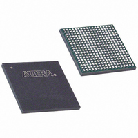
EP20K100EFC324-2 Altera, EP20K100EFC324-2 Datasheet - Page 14

EP20K100EFC324-2
Manufacturer Part Number
EP20K100EFC324-2
Description
IC APEX 20KE FPGA 100K 324-FBGA
Manufacturer
Altera
Series
APEX-20K®r
Datasheet
1.EP20K30ETC144-3.pdf
(117 pages)
Specifications of EP20K100EFC324-2
Number Of Logic Elements/cells
4160
Number Of Labs/clbs
416
Total Ram Bits
53248
Number Of I /o
246
Number Of Gates
263000
Voltage - Supply
1.71 V ~ 1.89 V
Mounting Type
Surface Mount
Operating Temperature
0°C ~ 85°C
Package / Case
324-FBGA
Family Name
APEX 20K
Number Of Usable Gates
100000
Number Of Logic Blocks/elements
4160
# Registers
26
# I/os (max)
246
Frequency (max)
250MHz
Process Technology
SRAM
Operating Supply Voltage (typ)
1.8V
Logic Cells
4160
Ram Bits
53248
Device System Gates
263000
Operating Supply Voltage (min)
1.71V
Operating Supply Voltage (max)
1.89V
Operating Temp Range
0C to 85C
Operating Temperature Classification
Commercial
Mounting
Surface Mount
Pin Count
324
Package Type
FBGA
Lead Free Status / RoHS Status
Contains lead / RoHS non-compliant
Available stocks
Company
Part Number
Manufacturer
Quantity
Price
Company:
Part Number:
EP20K100EFC324-2
Manufacturer:
ALTERA
Quantity:
18
Company:
Part Number:
EP20K100EFC324-2
Manufacturer:
PANASONIC
Quantity:
86
Company:
Part Number:
EP20K100EFC324-2
Manufacturer:
ALTERA
Quantity:
25
Company:
Part Number:
EP20K100EFC324-2-3
Manufacturer:
VISHAY
Quantity:
15 000
Company:
Part Number:
EP20K100EFC324-2X
Manufacturer:
ALTERA
Quantity:
15
APEX 20K Programmable Logic Device Family Data Sheet
14
Each LE has two outputs that drive the local, MegaLAB, or FastTrack
Interconnect routing structure. Each output can be driven independently
by the LUT’s or register’s output. For example, the LUT can drive one
output while the register drives the other output. This feature, called
register packing, improves device utilization because the register and the
LUT can be used for unrelated functions. The LE can also drive out
registered and unregistered versions of the LUT output.
The APEX 20K architecture provides two types of dedicated high-speed
data paths that connect adjacent LEs without using local interconnect
paths: carry chains and cascade chains. A carry chain supports high-speed
arithmetic functions such as counters and adders, while a cascade chain
implements wide-input functions such as equality comparators with
minimum delay. Carry and cascade chains connect LEs 1 through 10 in an
LAB and all LABs in the same MegaLAB structure.
Carry Chain
The carry chain provides a very fast carry-forward function between LEs.
The carry-in signal from a lower-order bit drives forward into the higher-
order bit via the carry chain, and feeds into both the LUT and the next
portion of the carry chain. This feature allows the APEX 20K architecture
to implement high-speed counters, adders, and comparators of arbitrary
width. Carry chain logic can be created automatically by the Quartus II
software Compiler during design processing, or manually by the designer
during design entry. Parameterized functions such as library of
parameterized modules (LPM) and DesignWare functions automatically
take advantage of carry chains for the appropriate functions.
The Quartus II software Compiler creates carry chains longer than ten LEs
by linking LABs together automatically. For enhanced fitting, a long carry
chain skips alternate LABs in a MegaLAB
than one LAB skips either from an even-numbered LAB to the next even-
numbered LAB, or from an odd-numbered LAB to the next odd-
numbered LAB. For example, the last LE of the first LAB in the upper-left
MegaLAB structure carries to the first LE of the third LAB in the
MegaLAB structure.
Figure 6
with the carry chain. One portion of the LUT generates the sum of two bits
using the input signals and the carry-in signal; the sum is routed to the
output of the LE. The register can be bypassed for simple adders or used
for accumulator functions. Another portion of the LUT and the carry chain
logic generates the carry-out signal, which is routed directly to the carry-
in signal of the next-higher-order bit. The final carry-out signal is routed
to an LE, where it is driven onto the local, MegaLAB, or FastTrack
Interconnect routing structures.
shows how an n-bit full adder can be implemented in n + 1 LEs
™
structure. A carry chain longer
Altera Corporation


