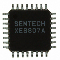
XE8807AMI026TLF Semtech, XE8807AMI026TLF Datasheet - Page 127

XE8807AMI026TLF
Manufacturer Part Number
XE8807AMI026TLF
Description
IC MCU LOW PWR MTP FLASH 32-TQFP
Manufacturer
Semtech
Datasheet
1.XE8807AMI026TLF.pdf
(143 pages)
Specifications of XE8807AMI026TLF
Applications
Sensing Machine
Core Processor
RISC
Program Memory Type
FLASH (11 kB)
Controller Series
XE8000
Ram Size
512 x 8
Interface
UART, USRT
Number Of I /o
24
Voltage - Supply
2.4 V ~ 5.5 V
Operating Temperature
-40°C ~ 85°C
Mounting Type
Surface Mount
Package / Case
32-TQFP, 32-VQFP
For Use With
XE8000MP - PROG BOARD AND PROSTART2 CARD
Lead Free Status / RoHS Status
Lead free / RoHS Compliant
Other names
XE8807AMI026TR
Available stocks
Company
Part Number
Manufacturer
Quantity
Price
Company:
Part Number:
XE8807AMI026TLF
Manufacturer:
IDT
Quantity:
62
The external clock sources can be debounced or not by properly setting the PortA configuration registers.
Additionally, the external clock sources can be divided by two in the counter block, thus enabling higher external
clock frequencies, by setting the CntXExtDiv bits in the RegCntOn register.
Switching between an internal and an external clock source can only be performed while the counter is stopped.
The enabling or disabling of the external clock frequency division can only be performed while the counter using
this clock is stopped, or when this counter is running on an internal clock source.
17.8 Counter mode selection
Each counter can work in one of the following modes:
The counters A and B or C and D can be cascaded or not. In cascaded mode, A and C are the LSB counters while
B and D are the MSB counters.
Table 17-12 shows the different operation modes of the counters A and B as a function of the mode control bits.
For all counter modes, the source of the down or upcount selection is given (either the bit CntADownUp or the bit
CntBDownUp). Also, the mapping of the interrupt sources IrqA and IrqB and the PWM output on PB(0) in these
different modes is shown.
Table 17-13 shows the different operation modes of the counters C and D as a function of the mode control bits.
For all counter modes, the source of the down or upcount selection is given (either the bit CntCDownUp or the bit
CntDDownUp). The mapping of the interrupt sources IrqC and IrqD and the PWM output on PB(1) in these
different modes is also shown.
The switching between different modes must be done while the concerned counters are stopped. While switching
capture mode on and off, unwanted interrupts can appear on the interrupt channels concerned by this mode
change.
© Semtech 2006
1) Counter, downcount & upcount
2) Captured counter, downcount & upcount (only counters A&B)
3) PWM, downcount & upcount
4) Captured PWM, downcount and upcount
CascadeAB
0
1
0
1
0
1
0
1
CountPWM0
0
0
1
1
0
0
1
1
CapFunc(1:0)
Table 17-12: Operating modes of the counters A and B
00
00
00
00
1x
x1
1x
x1
1x
x1
1x
x1
or
or
or
or
Counter 8b
Downup: A
Downup: A
Downup: A
Captured counter 16b AB
Downup: A
Counter A
counter 8b
Captured 10 – 16b PWM
(captured value on 16b)
Captured
Captured
PWM 8b
PWM 8b
mode
PWM 10 – 16b AB
Counter 16b AB
Downup: A
Downup: A
Downup: A
Downup A
17-6
Counter 8b
Downup: B
Counter 8b
Downup: B
Downup: B
Downup: B
Counter B
counter 8b
counter 8b
Captured
Captured
mode
Counter
Counter
Capture
Capture
Capture
Capture
source
IrqA
AB
AB
AB
A
A
A
-
-
XE8806A/XE8807A
Counter
Counter
Capture
Capture
Capture
Capture
source
IrqB
AB
AB
B
B
B
B
-
-
PWM AB
PWM AB
function
PWM A
PWM A
PB(0)
PB(0)
PB(0)
PB(0)
PB(0)
www.semtech.com


