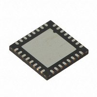
CY8CTMG201-32LQXI Cypress Semiconductor Corp, CY8CTMG201-32LQXI Datasheet - Page 166

CY8CTMG201-32LQXI
Manufacturer Part Number
CY8CTMG201-32LQXI
Description
IC MCU 16K FLASH PSOC 32UQFN
Manufacturer
Cypress Semiconductor Corp
Series
TrueTouch™r
Datasheet
1.CY8CTST200-16LGXI.pdf
(308 pages)
Specifications of CY8CTMG201-32LQXI
Applications
Touchscreen Controller
Core Processor
M8C
Program Memory Type
FLASH (16 kB)
Controller Series
CY8CT
Ram Size
2K x 8
Interface
I²C, SPI, UART/USART, USB
Number Of I /o
28
Voltage - Supply
1.8 V
Operating Temperature
-40°C ~ 85°C
Mounting Type
Surface Mount
Package / Case
32-UQFN Exposed Pad, 32-HUQFN, 32-SQFN
Processor Series
CY8CTxx2xx
Core
M8C
For Use With
770-1000 - ISP 4PORT FOR CYPRESS PSOC MCU
Lead Free Status / RoHS Status
Lead free / RoHS Compliant
Other names
428-2971
- Current page: 166 of 308
- Download datasheet (3Mb)
Table 20-1. Mode Encoding for Control and Non-Control Endpoints
20.2.2
The PSoC USB System Resource contains dedicated 512
bytes SRAM. This SRAM is identical to 2 SRAM pages used
in the PSoC Core; however, it is not accessible by way of the
M8C memory access instructions. The USB's dedicated
SRAM may only be accessed by way of the PMA registers.
For more information on how to use the USB's dedicated
SRAM, see the next section, PSoC Memory Arbiter (PMA).
The USB SRAM contents are not directly affected by any
reset, but must be treated as unknown after any POR, WDR,
and XRES.
20.2.2.1
The PSoC Memory Arbiter (PMA) is the interface between
the USB's dedicated SRAM and the two blocks that access
the SRAM: the M8C and the USB SIE. The PMA provides
16 channels to manage data with four Endpoints/8 channels
mapped to Page 0 of USB dedicated SRAM and other four
Endpoints/8 channels mapped to Page 1 of USB dedicated
SRAM. All of the channel registers may be used by the
M8C, but the eight non-control USB endpoints are each allo-
cated to a specific set of PMA channel registers. It is the
responsibility of the firmware to ensure that the M8C is not
accessing a set of channel registers that are in use by the
USB SIE.
Full-Speed USB
166
Disable
NAK IN/OUT
Status OUT Only
STALL IN/OUT
Reserved
ISO OUT
Status IN Only
ISO IN
NAK OUT
ACK OUT (STALL = 0)
ACK OUT (STALL = 1)
Reserved
ACK OUT – STATUS
IN
NAK IN
ACK IN (STALL = 0)
ACK IN (STALL = 1)
Reserved
ACK IN – Status OUT
Mode
USB SRAM
PSoC Memory Arbiter
0000
0001
0010
0011
0100
0101
0110
0111
1000
1001
1001
1010
1011
1100
1101
1101
1110
1111
Encoding
Ignore
Accept
Accept
Accept
Ignore
Ignore
Accept
Ignore
Ignore
Ignore
Ignore
Ignore
Accept
Ignore
Ignore
Ignore
Ignore
Accept
SETUP
Ignore
NAK
STALL
STALL
Ignore
Ignore
TX 0 Byte
TX Count
Ignore
Ignore
Ignore
Ignore
TX0 Byte
NAK
TX Count
STALL
Ignore
TX Count
PSoC CY8CTMG20x and CY8CTST200 TRM, Document No. 001-53603 Rev. *C
IN
Ignore
NAK
Check
STALL
Ignore
Always
STALL
Ignore
NAK
ACK
STALL
Ignore
ACK
Ignore
Ignore
Ignore
Ignore
Check
OUT
If the M8C wants to access the same data that an SIE chan-
nel is using, two channels must be configured to access the
same SRAM address ranges.
ping between PMA channels and which blocks can use
them.
Table 20-2. PMA Channel Assignments
Ignore all USB traffic to this endpoint.
NAK IN and OUT token.
For control endpoint, STALL IN and ACK zero byte OUT.
For control endpoint, STALL IN and OUT token.
Isochronous OUT.
For control endpoint, STALL OUT and send zero byte data for IN token.
Isochronous IN.
Send NAK handshake to OUT token.
This mode is changed by the SIE to mode 1000 on issuance of ACK hand-
shake to an OUT.
STALL the OUT transfer.
ACK the OUT token or send zero byte data for IN token.
Send NAK handshake for IN token.
This mode is changed by the SIE to mode 1100 after receiving ACK hand-
shake to an IN data.
STALL the IN transfer.
Respond to IN data or Status OUT.
Channel
PMA
10
11
12
13
14
15
0
1
2
3
4
5
6
7
8
9
EP1
EP2
EP3
EP4
EP5
EP6
EP7
EP8
USB SIE
Page 0
Page 0
Page 0
Page 0
Page 0
Page 0
Page 0
Page 0
Page 1
Page 1
Page 1
Page 1
Page 1
Page 1
Page 1
Page 1
M8C
Comments
PMA1_DR, PMA1_RA, PMA1_WA
PMA2_DR, PMA2_RA, PMA2_WA
PMA3_DR, PMA3_RA, PMA3_WA
PMA4_DR, PMA4_RA, PMA4_WA
PMA9_DR, PMA9_RA, PMA9_WA
PMA10_DR, PMA10_RA, PMA10_WA
PMA11_DR, PMA11_RA, PMA11_WA
PMA12_DR, PMA12_RA, PMA12_WA
PMA13_DR, PMA13_RA, PMA13_WA
PMA14_DR, PMA14_RA, PMA14_WA
PMA15_DR, PMA15_RA, PMA15_WA
PMA0_DR, PMA0_RA, PMA0_WA
PMA5_DR, PMA5_RA, PMA5_WA
PMA6_DR, PMA6_RA, PMA6_WA
PMA7_DR, PMA7_RA, PMA7_WA
PMA8_DR, PMA8_RA, PMA8_WA
Channel Registers (PMAx_xx)
Table 20-2
shows the map-
[+] Feedback
Related parts for CY8CTMG201-32LQXI
Image
Part Number
Description
Manufacturer
Datasheet
Request
R
Part Number:
Description:
IC MCU 16K FLASH PSOC 48-QFN
Manufacturer:
Cypress Semiconductor Corp
Datasheet:
Part Number:
Description:
IC MCU 16K FLASH PSOC 32UQFN
Manufacturer:
Cypress Semiconductor Corp
Part Number:
Description:
IC MCU 16K FLASH PSOC 48-QFN
Manufacturer:
Cypress Semiconductor Corp
Part Number:
Description:
Manufacturer:
Cypress Semiconductor Corp
Datasheet:
Part Number:
Description:
Manufacturer:
Cypress Semiconductor Corp
Datasheet:
Part Number:
Description:
Manufacturer:
Cypress Semiconductor Corp
Datasheet:
Part Number:
Description:
Manufacturer:
Cypress Semiconductor Corp
Datasheet:


