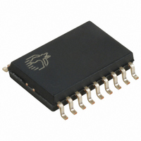
CY7C63231A-SC Cypress Semiconductor Corp, CY7C63231A-SC Datasheet - Page 29

CY7C63231A-SC
Manufacturer Part Number
CY7C63231A-SC
Description
IC MCU 3K USB LS PERIPH 18-SOIC
Manufacturer
Cypress Semiconductor Corp
Series
enCoRe™r
Datasheet
1.CY7C63231A-SXC.pdf
(50 pages)
Specifications of CY7C63231A-SC
Applications
USB Microcontroller
Core Processor
M8B
Program Memory Type
OTP (3 kB)
Controller Series
CY7C632xx
Ram Size
96 x 8
Interface
USB
Number Of I /o
10
Voltage - Supply
3.5 V ~ 5.5 V
Operating Temperature
0°C ~ 70°C
Mounting Type
Surface Mount
Package / Case
18-SOIC (7.5mm Width)
Operating Temperature (max)
70C
Operating Temperature (min)
0C
Operating Temperature Classification
Commercial
Package Type
SOIC
Mounting
Surface Mount
Lead Free Status / RoHS Status
Contains lead / RoHS non-compliant
Other names
428-1317
Available stocks
Company
Part Number
Manufacturer
Quantity
Price
Part Number:
CY7C63231A-SC
Manufacturer:
CYP
Quantity:
20 000
Bit [7:0]: Timer lower 8 bits
Bit [7:4]: Reserved
Bit [3:0]: Timer upper 4 bits
18.0
Bit 7: IRQ Pending
Document #: 38-08028 Rev. *B
Read/Write
Read/Write
Read/Write
Bit Name
Bit Name
Bit Name
When an interrupt is generated, it is registered as a pending interrupt. The interrupt will remain pending until its interrupt enable
bit is set (Figure 19-1 and Figure 19-2) and interrupts are globally enabled (Bit 2, Processor Status and Control Register). At
that point the internal interrupt handling sequence will clear the IRQ Pending bit until another interrupt is detected as pending.
This bit is only valid if the Global Interrupt Enable bit is disabled.
Reset
Reset
Reset
Bit #
Bit #
Bit #
Processor Status and Control Register
11
L3
D3
Pending
IRQ
R
7
0
7
0
R
7
0
-
10
L2
D2
9
L1
Figure 18-1. Processor Status and Control Register (Address 0xFF)
D1
Watchdog
Reset
R/W
8
L0
R
6
0
6
0
6
1
-
D0
Reserved
Figure 17-2. Timer MSB Register (Address 0x25)
Figure 17-1. Timer LSB Register (Address 0x24)
FOR
FOR
7
D7
Interrupt
Figure 17-3. Timer Block Diagram
6
Event
R/W
Bus
D6
R
5
0
5
0
5
0
-
5
D5
4
LVR/BOR
Reset
D4
R/W
R
4
0
4
0
4
1
-
3
Timer [7:0]
D3
2
Suspend
D2
R/W
R
R
3
0
3
0
3
0
1
D1
8
0
D0
Interrupt
Enable
Sense
R
R
R
2
0
2
0
2
0
Timer [11:8]
CY7C63221/31A
1.024-ms interrupt
128-
1 MHz clock
To Timer Registers
enCoRe™ USB
µ
Reserved
s interrupt
R
R
1
0
1
0
1
0
-
Page 29 of 50
R/W
Run
R
R
0
1
0
0
0
0
[+] Feedback


