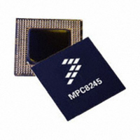
MPC8245LVV333D Freescale Semiconductor, MPC8245LVV333D Datasheet - Page 28

MPC8245LVV333D
Manufacturer Part Number
MPC8245LVV333D
Description
IC MPU 32BIT 333MHZ PPC 352-TBGA
Manufacturer
Freescale Semiconductor
Series
PowerQUICC IIr
Specifications of MPC8245LVV333D
Processor Type
MPC82xx PowerQUICC II 32-bit
Speed
333MHz
Voltage
2V
Mounting Type
Surface Mount
Package / Case
352-TBGA
Processor Series
MPC8xxx
Core
603e
Data Bus Width
32 bit
Maximum Clock Frequency
333 MHz
Operating Supply Voltage
2 V, 2.1 V, 3.3 V
Maximum Operating Temperature
+ 105 C
Mounting Style
SMD/SMT
Minimum Operating Temperature
0 C
Core Size
32 Bit
Program Memory Size
32KB
Cpu Speed
333MHz
Embedded Interface Type
I2C, UART
Digital Ic Case Style
TBGA
No. Of Pins
352
Supply Voltage Range
1.9V To 2.2V
Rohs Compliant
Yes
Lead Free Status / RoHS Status
Lead free / RoHS Compliant
Features
-
Lead Free Status / Rohs Status
Lead free / RoHS Compliant
Available stocks
Company
Part Number
Manufacturer
Quantity
Price
Company:
Part Number:
MPC8245LVV333D
Manufacturer:
Maxim
Quantity:
52
Company:
Part Number:
MPC8245LVV333D
Manufacturer:
FREESCAL
Quantity:
1 045
Company:
Part Number:
MPC8245LVV333D
Manufacturer:
Freescale Semiconductor
Quantity:
10 000
Part Number:
MPC8245LVV333D
Manufacturer:
FREESCALE
Quantity:
20 000
Electrical and Thermal Characteristics
Figure 17
4.7
Table 14
recommended operating conditions (see
28
Notes:
1. See the MPC8245 Integrated Processor Reference Manual for a description of the PIC interrupt control register (ICR) and
2. S_RST, S_FRAME, and S_INT shown in
3. The sys_logic_clk waveform is the clocking signal of the internal peripheral logic from the output of the peripheral logic PLL;
Num
1
2
3
4
5
6
7
S_CLK frequency programming.
and do not describe functional relationships between S_RST, S_FRAME, and S_INT. The MPC8245 Integrated Processor
Reference Manual describes the functional relationships between these signals.
sys_logic_clk is the same as SDRAM_SYNC_IN when the SDRAM_SYNC_OUT to SDRAM_SYNC_IN feedback loop is
implemented and the DLL is locked. See the MPC8245 Integrated Processor Reference Manual for a complete clocking
description.
SDA
SCL
S_CLK frequency
S_CLK duty cycle
S_CLK output valid time
Output hold time
S_FRAME, S_RST output valid time
S_INT input setup time to S_CLK
S_INT inputs invalid (hold time) to S_CLK
provides the PIC serial interrupt mode AC timing specifications for the MPC8245 at
PIC Serial Interrupt Mode AC Timing Specifications
shows the AC timing diagram for the I
S
t
I2CF
Characteristic
t
I2CL
t
I2SXKL
Table 14. PIC Serial Interrupt Mode AC Timing Specifications
MPC8245 Integrated Processor Hardware Specifications, Rev. 10
Figure 17. I
t
I2DXKL,
Figure 18
t
Table
I2DVKH
t
I2OVKL
1 sys_logic_clk period + 2
1/14 SDRAM_SYNC_IN
t
I2CH
2
C Bus AC Timing Diagram
and
2) with GV
t
2
I2SXKL
Figure
C bus.
Min
40
—
—
—
0
19, depict timing relationships to sys_logic_clk and S_CLK
Sr
DD
t
I2SVKH
= 3.3 V ± 5% and LV
t
I2KHKL
1 sys_logic_clk period + 6
1/2 SDRAM_SYNC_IN
t
Max
I2PVKH
60
—
—
6
0
t
I2CR
DD
Freescale Semiconductor
P
= 3.3 V ± 0.3 V.
t
I2CF
MHz
Unit
ns
ns
ns
ns
ns
%
S
Notes
—
—
—
1
2
2
2


