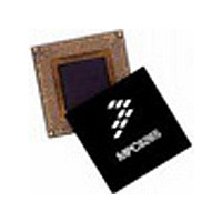
MPC8250ACVVMHBC Freescale Semiconductor, MPC8250ACVVMHBC Datasheet - Page 10

MPC8250ACVVMHBC
Manufacturer Part Number
MPC8250ACVVMHBC
Description
IC MPU POWERQUICC II 480-TBGA
Manufacturer
Freescale Semiconductor
Datasheet
1.MPC8250AVRIHBC.pdf
(62 pages)
Specifications of MPC8250ACVVMHBC
Processor Type
MPC82xx PowerQUICC II 32-bit
Speed
266MHz
Voltage
2V
Mounting Type
Surface Mount
Package / Case
480-TBGA
Family Name
MPC82XX
Device Core
PowerQUICC II
Device Core Size
32b
Frequency (max)
266MHz
Instruction Set Architecture
RISC
Operating Supply Voltage (max)
2.2V
Operating Supply Voltage (min)
1.9V
Operating Temp Range
-40C to 105C
Operating Temperature Classification
Industrial
Mounting
Surface Mount
Pin Count
480
Package Type
TBGA
Leaded Process Compatible
Yes
Rohs Compliant
Yes
Peak Reflow Compatible (260 C)
Yes
For Use With
CWH-PPC-8248N-VE - KIT EVAL SYSTEM QUICCSTART 8248
Lead Free Status / RoHS Status
Lead free / RoHS Compliant
Features
-
Lead Free Status / Rohs Status
Compliant
Available stocks
Company
Part Number
Manufacturer
Quantity
Price
Company:
Part Number:
MPC8250ACVVMHBC
Manufacturer:
FREESCAL
Quantity:
390
Company:
Part Number:
MPC8250ACVVMHBC
Manufacturer:
Freescale Semiconductor
Quantity:
10 000
Part Number:
MPC8250ACVVMHBC
Manufacturer:
FREESCALE
Quantity:
20 000
Electrical and Thermal Characteristics
2.2
Table 4
2.3
The average chip-junction temperature
where
For most applications P
T
Solving equations (1) and (2) for K gives:
10
J
is the following:
1
2
3
1
2
Junction to ambient—
single-layer board
Junction to ambient—
four-layer board
Junction to board
Junction to case
measured on the top surface of the board near the package.
Method 1012.1).
Thermal resistance between the die and the case top surface as measured by the cold plate method (MIL SPEC-883
Assumes no thermal vias
Thermal resistance between the die and the printed circuit board per JEDEC JESD51-8. Board temperature is
DC current, it is recommended to either pull unused pins to GND or VDDH, or to configure them as outputs.
The default configuration of the CPM pins (PA[0–31], PB[4–31], PC[0–31], PD[4–31]) is input. To prevent excessive
The leakage current is measured for nominal VDD, VCCSYN, and VDD.
T
T
θ
P
P
P
P
K = P
describes thermal characteristics.
Characteristic
A
INT
I/O
D
JA
J
D
Thermal Characteristics
Power Considerations
= T
= ambient temperature °C
= K/(T
= P
= package thermal resistance
= power dissipation on input and output pins (determined by user)
= I
D
A
INT
DD
x (T
+ (P
J
x V
+ 273° C)
+ P
A
3
D
2
1
+ 273° C) +
x
DD
I/O
θ
I/O
JA
Watts (chip internal power)
)
< 0.3 x P
Symbol
θ
θ
θ
θ
JA
JB
JC
JA
MPC8250 Hardware Specifications, Rev. 2
x P
INT
Table 4. Thermal Characteristics
,
junction to ambient
,
D
. If P
T
2
J
,
480 TBGA
in °C can be obtained from the following:
I/O
1.1
13
10
11
8
4
is neglected
Value
,
°C/W
516 PBGA
,
an approximate relationship between P
24
18
16
13
8
6
°C/W
°C/W
°C/W
Unit
Freescale Semiconductor
Natural convection
Natural convection
Air Flow
1 m/s
1 m/s
—
—
(3)
(1)
(2)
D
and


