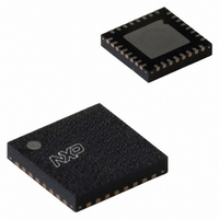
UDA1380HN/N2,118 NXP Semiconductors, UDA1380HN/N2,118 Datasheet - Page 20

UDA1380HN/N2,118
Manufacturer Part Number
UDA1380HN/N2,118
Description
IC AUDIO CODEC MINIDISC 32HVQFN
Manufacturer
NXP Semiconductors
Type
Stereo Audior
Datasheet
1.UDA1380HNN2118.pdf
(68 pages)
Specifications of UDA1380HN/N2,118
Package / Case
32-VFQFN Exposed Pad
Data Interface
I²C, Serial
Resolution (bits)
24 b
Number Of Adcs / Dacs
2 / 2
Sigma Delta
No
S/n Ratio, Adcs / Dacs (db) Typ
97 / 100
Voltage - Supply, Analog
2.4 V ~ 3.6 V
Voltage - Supply, Digital
2.4 V ~ 3.6 V
Operating Temperature
-40°C ~ 85°C
Mounting Type
Surface Mount
Interface Type
Serial (I2C)
Resolution
24 bit
Operating Supply Voltage
3 V
Maximum Operating Temperature
+ 85 C
Mounting Style
SMD/SMT
Minimum Operating Temperature
- 40 C
Supply Current
10 mA
Thd Plus Noise
- 85 dB
Lead Free Status / RoHS Status
Lead free / RoHS Compliant
Lead Free Status / RoHS Status
Lead free / RoHS Compliant, Lead free / RoHS Compliant
Other names
935271001118
UDA1380HN-T
UDA1380HN-T
UDA1380HN-T
UDA1380HN-T
NXP Semiconductors
8.13
The supported audio formats for the control modes are:
• I
• MSB-justified
• LSB-justified, 16 bits
• LSB-justified, 18 bits
• LSB-justified, 20 bits
• LSB-justified, 24 bits (only for the output interface).
The bit clock BCK can be up to 128f
BCK frequency is 128 times the WS frequency or less:
f
Remark: The WS edge must coincide with the negative
edge of the BCK at all times, for proper operation of the
digital I/O data interface. Figure 13 shows the interface
signals.
8.13.1
The digital audio input interface is slave only, meaning the
system must provide the WSI and BCKI signals (next to
the DATAI signal).
Either the WSPLL locks onto the WSI signal and provides
the internal clocks for the interpolator and the FSDAC, or
a system clock must be applied which must be in
frequency lock to the digital data input interface signals.
8.13.2
The digital audio output interface can be either master or
slave. The data source for the data output can be selected
from either the decimator (ADC front-end) or the digital
mixer output.
Remark: The digital mixer output is only valid if both the
decimator and the interpolator run at the same clock:
• In slave mode the signals on pins BCKO, WSO and
• In master mode the SYSCLK signal must be applied
2004 Apr 22
BCK
SYSCLK must be applied from the application (signals
must be in frequency lock) and the UDA1380 returns the
DATAO signal from the decimator. The applied signal
from pin BCKO can be for instance: 32f
96f
from the system, then the UDA1380 returns with the
BCKO, WSO and the DATAO signals. For the BCKO
clock, there are 2 general rules:
– When the SYSCLK is either 256f
– When the SYSCLK is either 384f
Stereo audio coder-decoder
for MD, CD and MP3
2
S-bus
≤ 128f
frequency is 64f
signal is 48f
s
or 128f
Digital audio data input and output
D
D
IGITAL AUDIO INPUT INTERFACE
IGITAL AUDIO OUTPUT INTERFACE
WS
.
s
s
.
s
s
, or in other words the
s
s
or 512f
or 768f
s
, 48f
s
s
, the BCKO
, the BCKO
s
, 64f
s
,
20
The slave and master modes can be selected by the
bit Serial Interface Mode (SIM) in the L3-bus or I
interface.
9
The UDA1380 has an L3-bus microcontroller
interface mode. Controllable system and digital sound
processing features are:
• Software reset
• System clock frequency (selection between 256f
• Clock mode setting, for instance, which block runs at
• Power control for the WSPLL
• Data input and data output format control, for input and
• ADC features:
• DAC and headphone driver features:
512f
which clock, and clock enabling
output independently including data source selection for
the digital output interface
– Digital mute
– AGC enable and settings
– Polarity control
– Input line amplifier control (0 to 24 dB in steps of
– DC filtering control
– Digital gain control (+24 to −63 dB gain in steps of
– Power control
– VGA of the microphone input
– Selection of line or microphone input.
– Power control FSDAC and headphone driver
– Polarity control
– Mixing control (only available when both decimator
– De-emphasis control
– Master volume and balance control
– Flat/minimum/maximum settings for bass boost and
– Tone control: bass boost and treble
– Master mute control
– Headphone driver short-circuit protection status bits.
L3-BUS INTERFACE DESCRIPTION
3 dB)
0.5 dB) for left and right
and interpolator run at the same speed). This
includes the mixer volumes, mute and mixer position
switch
treble
s
and 768f
s
clock divider settings)
Product specification
UDA1380
2
C-bus
s
, 384f
s
,


