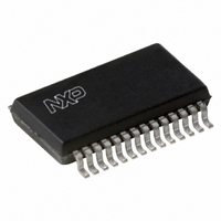
UDA1342TS/N1,518 NXP Semiconductors, UDA1342TS/N1,518 Datasheet - Page 20

UDA1342TS/N1,518
Manufacturer Part Number
UDA1342TS/N1,518
Description
IC AUDIO CODEC 24BIT 28SSOP
Manufacturer
NXP Semiconductors
Type
Stereo Audior
Datasheet
1.UDA1342TSN1518.pdf
(45 pages)
Specifications of UDA1342TS/N1,518
Package / Case
28-SSOP (0.200", 5.30mm Width)
Data Interface
Serial
Resolution (bits)
24 b
Number Of Adcs / Dacs
4 / 2
Sigma Delta
No
S/n Ratio, Adcs / Dacs (db) Typ
99 / 99
Voltage - Supply, Analog
2.7 V ~ 3.6 V
Voltage - Supply, Digital
2.7 V ~ 3.6 V
Operating Temperature
-40°C ~ 85°C
Mounting Type
Surface Mount
Number Of Adc Inputs
4
Number Of Dac Outputs
2
Conversion Rate
110 KSPS
Interface Type
Serial (I2C) or L3
Resolution
24 bit
Maximum Operating Temperature
+ 85 C
Mounting Style
SMD/SMT
Minimum Operating Temperature
- 40 C
Number Of Channels
4 ADC / 2 DAC
Lead Free Status / RoHS Status
Lead free / RoHS Compliant
Lead Free Status / RoHS Status
Lead free / RoHS Compliant, Lead free / RoHS Compliant
Other names
935262909518
UDA1342TSDB-T
UDA1342TSDB-T
UDA1342TSDB-T
UDA1342TSDB-T
8.16.5
The read cycle is used to read data from the internal registers of the UDA1342TS to the microcontroller. The I
in Table 18.
The format of the read cycle is as follows:
1. The microcontroller starts with a START condition S.
2. The first byte (8 bits) contains the device address 0011 01X and a write command (bit R/W = 0).
3. This is followed by an acknowledge (A) from the UDA1342TS.
4. The microcontroller then writes the register address where reading of the register content of the UDA1342TS must start.
5. The UDA1342TS acknowledges this register address.
6. Then the microcontroller generates a repeated START (Sr).
7. Again the device address 0011 01X is given, but this time followed by a read command (bit R/W = 1).
8. The UDA1342TS sends the two-byte data with the Most Significant Data (MSD) byte first and then the Least Significant Data (LSD) byte, where
9. The microcontroller stops this cycle by generating a negative acknowledge (NA).
10. The UDA1342TS then frees the I
Table 18 Master transmitter reads from UDA1342TS registers
Note
1. Auto increment of the register address is carried out if repeated groups of 2 bytes are transmitted.
S
each byte is acknowledged by the microcontroller (master).
ADDRESS
0011 01X
DEVICE
R
EAD CYCLE
8 bits
R/W
0
A 0XXX XXXX A Sr
ACKNOWLEDGE FROM UDA1342TS
REGISTER
ADDRESS
8 bits
2
C-bus and the microcontroller can generate a STOP condition (P).
ADDRESS
0011 01X
DEVICE
8 bits
R/W
1
A MSD1 A LSD1 A MSD2 A LSD2 A MSDn A LSDn
8 bits
8 bits
ACKNOWLEDGE FROM MASTER
8 bits
DATA
2
8 bits
C-bus format for a read cycle is shown
(1)
8 bits
8 bits
NA P


