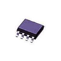
SE95D NXP Semiconductors, SE95D Datasheet - Page 7

SE95D
Manufacturer Part Number
SE95D
Description
Board Mount Temperature Sensors I2C LOCAL +/- 1OC TS
Manufacturer
NXP Semiconductors
Datasheet
1.SE95D118.pdf
(27 pages)
Specifications of SE95D
Full Temp Accuracy
+/- 3 C
Package / Case
SOT-96
Digital Output - Bus Interface
2-Wire
Digital Output - Number Of Bits
13 bit
Maximum Operating Temperature
+ 125 C
Minimum Operating Temperature
- 55 C
Output Type
Digital
Lead Free Status / Rohs Status
Lead free / RoHS Compliant
Other names
SE95D,112
Available stocks
Company
Part Number
Manufacturer
Quantity
Price
Part Number:
SE95D
Manufacturer:
NXP/恩智浦
Quantity:
20 000
Part Number:
SE95DP
Manufacturer:
NXP/恩智浦
Quantity:
20 000
Part Number:
SE95DP,118
Manufacturer:
NXP/恩智浦
Quantity:
20 000
NXP Semiconductors
8. I
SE95_7
Product data sheet
2
C-bus serial interface
7.5 Shutdown mode
7.6 Power-up default and power-on reset
8.1 Slave address
The device operation mode is selected by programming bit SHUTDOWN of register Conf.
Setting bit SHUTDOWN to logic 1 will put the device into shutdown mode. Resetting bit
SHUTDOWN to logic 0 will return the device to normal mode.
In shutdown mode, the device draws a small current of approximately 7.5 A and the
power dissipation is minimized; the temperature conversion stops, but the I
interface remains active and register write/read operation can be performed. If the OS
output is in comparator mode, then it remains unchanged. In interrupt mode, the OS
output is reset.
The SE95 always powers-up in its default state with:
When the power supply voltage is dropped below the device power-on reset level of
approximately 1.9 V (POR) and then rises up again, the device will be reset to its default
condition as listed above.
The SE95 can be connected to a compatible 2-wire serial interface I
device under the control of a controller or master device, using two device terminals, SCL
and SDA. The controller must provide the SCL clock signal and write/read data to and
from the device through the SDA terminal. Note that if the I
resistors have not been installed as required for I
approximately 10 k , is needed for each of these two terminals. The bus communication
protocols are described in
The SE95 slave address on the I
device address pins A2, A1 and A0. Each pin is typically connected either to GND for
logic 0, or to V
address. The other four MSB bits of the address data are preset to 1001 by hard wiring
inside the SE95.
8 devices can be connected to the same bus without address conflict. Because the input
pins SCL, SDA and A2 to A0, are not internally biased, it is important that they should not
be left floating in any application.
0Ch is a reserved address for SMBus Alert Response Address (ARA). This is an optional
command from the SMBus specification to allow SMBus devices to respond to an SMBus
master with their slave device if they are generating an interrupt. The SE95 will send a
•
•
•
•
•
•
Normal operation mode
OS comparator mode
T
T
OS output active state is LOW
Pointer value is logic 0
os
hyst
= 80 C
= 75 C
CC
Ultra high accuracy digital temperature sensor and thermal watchdog
Table 4
for logic 1. These pins represent the three LSB bits of the device 7-bit
Rev. 07 — 2 September 2009
shows the device's complete address and indicates that up to
Section 8.7 “Protocols for writing and reading the
2
C-bus is partially defined by the logic applied to the
2
C-bus, then an external pull-up resistor,
2
C-bus common pull-up
2
C-bus as a slave
© NXP B.V. 2009. All rights reserved.
2
C-bus
registers”.
SE95
7 of 27


