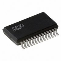
UDA1342TS/N1,512 NXP Semiconductors, UDA1342TS/N1,512 Datasheet - Page 22

UDA1342TS/N1,512
Manufacturer Part Number
UDA1342TS/N1,512
Description
IC AUDIO CODEC MINIDISC 28-SSOP
Manufacturer
NXP Semiconductors
Type
Stereo Audior
Datasheet
1.UDA1342TSN1518.pdf
(45 pages)
Specifications of UDA1342TS/N1,512
Package / Case
28-SSOP (0.200", 5.30mm Width)
Data Interface
Serial
Resolution (bits)
24 b
Number Of Adcs / Dacs
4 / 2
Sigma Delta
No
S/n Ratio, Adcs / Dacs (db) Typ
99 / 99
Voltage - Supply, Analog
2.7 V ~ 3.6 V
Voltage - Supply, Digital
2.7 V ~ 3.6 V
Operating Temperature
-40°C ~ 85°C
Mounting Type
Surface Mount
Number Of Adc Inputs
4
Number Of Dac Outputs
2
Conversion Rate
110 KSPs
Interface Type
Serial (I2C), L3
Resolution
24 bit
Operating Supply Voltage
2.7 V to 3.6 V
Maximum Operating Temperature
+ 85 C
Mounting Style
SMD/SMT
Minimum Operating Temperature
- 40 C
Number Of Channels
4 ADC, 2 DAC
Supply Current
20 mA
Lead Free Status / RoHS Status
Lead free / RoHS Compliant
Other names
568-1155-5
935262909512
UDA1342TSDB
935262909512
UDA1342TSDB
NXP Semiconductors
9.1
A 1-bit value to initialize the L3-bus and I
except the system register (00H) with default settings by
setting bit RST = 1.
Table 20 Reset bit
9.2
A 1-bit value to enable the quick mode change of the ADC.
The soft mode change works only between modes if
bit AM2 = 1.
Table 21 Quick mode switch
9.3
A 1-bit value to disable the DC filter of the ADC mixer. This
DC filter is in front of the mixer to prevent clipping inside
the mixer due to DC signals.
Table 22 Mixer DC filtering
9.4
A 1-bit value to enable the DC filter of the ADC output. This
DC filter is inside the decimation filter.
Table 23 DC-filtering
2000 Jul 31
Audio CODEC
MDC
RST
QS
DC
Reset
Quick mode switch
Bypass mixer DC filter
DC filter
0
1
0
1
0
1
0
1
no reset
reset registers to default
soft mode change
quick mode change
enable mixer DC filtering
disable mixer DC filtering
disable output DC filtering
enable output DC filtering
FUNCTION
FUNCTION
FUNCTION
FUNCTION
2
C-bus registers
22
9.5
A 3-bit value to select the mode of the ADC.
Table 24 ADC mode
9.6
A 1-bit value to control the ADC polarity.
Table 25 Polarity control of the ADC
9.7
A 2-bit value to select the external clock frequency.
Table 26 System clock frequency settings
AM2 AM1 AM0
0
0
0
0
1
1
1
1
SC1
0
0
1
1
System clock frequency
ADC mode
ADC polarity
PAD
0
0
1
1
0
0
1
1
0
1
SC0
0
1
0
1
0
1
0
1
0
1
0
1
ADC power-off
input 1 select (input 2 off)
input 2 select (input 1 off)
not used
channel swap and signal inversion
input 1 select (double differential
mode)
input 2 select (double differential
mode)
mixing mode
non-inverting
inverting
256f
384f
512f
768f
s
s
s
s
FUNCTION
FUNCTION
FUNCTION
UDA1342TS
Product specification


