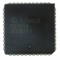
PEB2075N-V13TR Infineon Technologies, PEB2075N-V13TR Datasheet - Page 38

PEB2075N-V13TR
Manufacturer Part Number
PEB2075N-V13TR
Description
IC CONTROLLER D-CH EXCH 44-PLCC
Manufacturer
Infineon Technologies
Datasheet
1.PEB2075N-V13TR.pdf
(81 pages)
Specifications of PEB2075N-V13TR
Controller Type
Digital Exchange Controller
Interface
PCM
Voltage - Supply
4.75 V ~ 5.25 V
Current - Supply
10mA
Operating Temperature
0°C ~ 70°C
Mounting Type
Surface Mount
Package / Case
44-PLCC
Lead Free Status / RoHS Status
Contains lead / RoHS non-compliant
Other names
PEB2075N-V13INTR
PEB2075N-V13TR
PEB2075N-V13TR
Available stocks
Company
Part Number
Manufacturer
Quantity
Price
Company:
Part Number:
PEB2075N-V13TR
Manufacturer:
LT
Quantity:
512
Company:
Part Number:
PEB2075N-V13TR
Manufacturer:
Infineon Technologies
Quantity:
10 000
Functional Description
In the TS mode the time slot programmed via the Time-Slot Select Register TSR applies
simultaneously to SD0X/SD0R and to the auxiliary lines CDR, SD1X and SD2X. In the IOM mode
the TSR register selects a time channel on the auxiliary connections CDR, SD1X and SD2X only
(however, the channel width selected should be two bits, as on the IOM interface, to ensure a
correct data throughput).
The switching of data from SD0R to SD1X is transparent. The switching of data from CDR to SD0X
depends on the state of the HDLC controller (transmit/no transmit) and on selected priorities, as
follows.
When no transmission command is issued to the HDLC controller, data is transparently switched
through from CDR to SD0X. When a transmit request is issued but the Force HDLC Frame (FHF)
bit is not set to 1, the data currently being received (if any) on CDR is given priority. The HDLC
controller starts transmitting its frame on SD0X only after CDR is detected to be idle, in other words,
when a row of eight ones is observed on CDR. Simultaneously, SD2X is set "low" to indicate that
no data will be accepted on CDR input data line.
Figure 15a shows the time relation between CDR (data in) and SD2X (collision out) as well as the
logical relation between SD2X and SD0X (data out). The figures are simplified in that the grouping
of bits into time slots on SD0X, and on SD2X/CDR is not depicted.
When a transmit command is issued and the Force HDLC Frame (FHF) bit is set to 1, the frame
currently being received on CDR is aborted. Seven ones are appended to the last bit of the aborted
frame on SD0X, after which the HDLC controller starts transmitting its frame (figure 15b).
In both cases, SD2X is set "high" again after a delay of eight bit-times following the last "0" of the
closing flag, to indicate that data is accepted on the CDR input data line. However, if a new transmit
command is issued before that time, SD2X remains "low" and transmission of the new frame starts
immediately after the eighth 1.
Semiconductor Group
38


