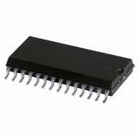
SJA1000T/N,112 NXP Semiconductors, SJA1000T/N,112 Datasheet - Page 27

SJA1000T/N,112
Manufacturer Part Number
SJA1000T/N,112
Description
IC STAND-ALONE CAN CTRLR 28-SOIC
Manufacturer
NXP Semiconductors
Datasheet
1.SJA1000TN1112.pdf
(68 pages)
Specifications of SJA1000T/N,112
Controller Type
CAN Interface
Interface
CAN
Voltage - Supply
4.5 V ~ 5.5 V
Current - Supply
15mA
Operating Temperature
-40°C ~ 125°C
Mounting Type
Surface Mount
Package / Case
28-SOIC (7.5mm Width)
Lead Free Status / RoHS Status
Lead free / RoHS Compliant
Other names
935277294112
SJA1000T/N
SJA1000T/N
SJA1000T/N
SJA1000T/N
Philips Semiconductors
Notes
1. The SJA1000 will enter sleep mode if the sleep mode bit is set to logic 1 (sleep); then there is no bus activity and no
2. A write access to the bits MOD.1 to MOD.3 is only possible, if the reset mode is entered previously.
3. This mode of operation forces the CAN controller to be error passive. Message transmission is not possible.
4. During a hardware reset or when the bus status bit is set to logic 1 (bus-off), the reset mode bit is also set to logic 1
2000 Jan 04
MOD.1
MOD.0
Stand-alone CAN controller
interrupt is pending. Setting of SM with at least one of the previously mentioned exceptions valid will result in a
wake-up interrupt. After sleep mode is set, the CLKOUT signal continues until at least 15 bit times have passed, to
allow a host microcontroller clocked via this signal to enter its own standby mode before the CLKOUT goes LOW.
The SJA1000 will wake up when one of the three previously mentioned conditions is negated: after SM is set LOW
(wake-up), there is bus activity or INT is driven LOW (active). On wake-up, the oscillator is started and a wake-up
interrupt is generated. A sleeping SJA1000 which wakes up due to bus activity will not be able to receive this
message until it detects 11 consecutive recessive bits (bus-free sequence). It should be noted that setting of SM is
not possible in reset mode. After clearing of reset mode, setting of SM is possible first, when bus-free is detected
again.
The listen only mode can be used e.g. for software driven bit rate detection and ‘hot plugging’. All other functions can
be used like in normal mode.
(present). If this bit is accessed by software, a value change will become visible and takes effect first with the next
positive edge of the internal clock which operates at half of the external oscillator frequency. During an external reset
the microcontroller cannot set the reset mode bit to logic 0 (absent). Therefore, after having set the reset mode bit to
logic 1, the microcontroller must check this bit to ensure that the external reset pin is not being held HIGH. Changes
of the reset request bit are synchronized with the internal divided clock. Reading the reset request bit reflects the
synchronized status. After the reset mode bit is set to logic 0 the CAN controller will wait for:
a) One occurrence of bus-free signal (11 recessive bits), if the preceding reset has been caused by a hardware reset
b) 128 occurrences of bus-free, if the preceding reset has been caused by a CAN controller initiated bus-off, before
BIT
or a CPU-initiated reset.
re-entering the bus-on mode.
LOM
RM
SYMBOL
Listen Only Mode;
notes 2 and 3
Reset Mode; note 4
NAME
VALUE
27
1
0
1
0
listen only; in this mode the CAN controller would
give no acknowledge to the CAN-bus, even if a
message is received successfully; the error
counters are stopped at the current value
normal
reset; detection of a set reset mode bit results in
aborting the current transmission/reception of a
message and entering the reset mode
normal; on the ‘1-to-0’ transition of the reset mode
bit, the CAN controller returns to the operating
mode
FUNCTION
Product specification
SJA1000


