PMR8210P Ericsson Power Modules, PMR8210P Datasheet - Page 10
PMR8210P
Manufacturer Part Number
PMR8210P
Description
DC/DC Switching Controllers PoL Regul in 4.5-14V O/P 0.7-3.6 50A
Manufacturer
Ericsson Power Modules
Datasheet
1.PMR8210SR.pdf
(21 pages)
Specifications of PMR8210P
Number Of Outputs
1
Output Voltage
3 V to 5.25 V
Output Current
40 A
Output Power
132 W
Switching Frequency
600 KHz
Maximum Operating Temperature
+ 85 C
Minimum Operating Temperature
- 40 C
Lead Free Status / Rohs Status
Lead free / RoHS Compliant


Inhibit Control
When the Inhibit pin is left open, the regulator will turn on
when the input voltage is applied. Turn off is achieved by
connecting the Inhibit pin to the GND.
The reference figure above shows the typical application of
the inhibit function. The input is not compatible with TTL logic
device. An open-collector (or open-drain) discrete transistor is
recommended for control. Turning the discrete transistor on
applies a low voltage to the Inhibit control pin and disables the
output of the module. If this device is then turned off, the
module executes a soft-start power-up sequence. A regulated
output voltage is produced within 20 ms.
External Decoupling Capacitors
Input capacitors:
The PMR 8210 requires a minimum input capacitance of e
1000 µF. The ripple current rating of the input capacitor must
be at least 750 mA rms. An optional 22 µF X5R/X7R ceramic
capacitor is recommended to reduce RMS ripple current.
The size and value of the input capacitor is determined by the
converter’s transient performance capability. This minimum
value assumes that the converter is supplied with a
responsive, low inductance input source. This source should
have ample capacitive decoupling, and be distributed to the
converter via PCB power and ground planes.
Ceramic capacitors should be located as close as possible to
the module's input pins, within 0.5 inch (1,3 cm). Adding
ceramic capacitance is necessary to reduce the high-
frequency ripple voltage at the module's input. This reduces
the magnitude of the ripple current through the electrolytic
capacitor, as well as the amount of ripple current reflected
back to the input source. Additional ceramic capacitors can be
added to further reduce the RMS ripple current requirement
for the electrolytic capacitor.
The main considerations when selecting input capacitors are
the RMS ripple current rating, temperature stability, and less
than 100 mΩ of equivalent series resistance (ESR).
Regular tantalum capacitors are not recommended for the
input bus. These capacitors require a recommended
E
Prepared (also subject responsible if other)
ECOCOLO
Approved
SEC/D (Julia You)
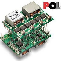
PMR 8000 series PoL Regulator
Input 8 - 14 V, Output up to 40 A / 210 W
The products are fitted with
a remote control function
by using the Inhibit/UVLO
pin. The Inhibit control
function allows the product
to be turned on/off by an
external device like a
semiconductor or
mechanical switch. The RC
pin has an internal pull up.
An external pull-up resistor
should never be used with
the inhibit pin.
Checked
EJANLLI
Ericsson Internal
PRODUCT SPECIFICATION
No.
3/1301-BMR 629 8210 Uen
Date
2009-09-28
minimum voltage rating of 2× (maximum dc voltage + ac
ripple). This is standard practice to ensure reliability. No
tantalum capacitors were found with a sufficient voltage rating
to meet this requirement.
Output capacitors:
The PMR 8210 module requires a minimum output
capacitance of 1000µF of polymer-aluminum, tantulum, or
polymer-tantalum type.
The required capacitance above the minimum is determined
by actual transient deviation requirements. See
“TurboTrans Technology” information below.
For both input and output capacitors, when the operating
temperature is below 0°C, the ESR of aluminium electrolytic
capacitors increases. For these applications, OS-CON, poly-
aluminium, and polymer-tantalum types should be considered.
If the TurboTrans feature is not used, minimum ESR and
maximum capacitor limits must be followed. System stability
may be effected and increased output capacitance may be
required without TurboTrans.
When using the PMR 8210, observe the minimum ESR of the
entire output capacitor bank. The minimum ESR limit of the
output capacitor bank is 7mΩ.
When using PMR 8210 without the TurboTrans feature, the
maximum amount of capacitance is 1000 µF of ceramic type.
Large amounts of capacitance may reduce system stability.
Utilizing the TurboTrans feature improves system stability,
improves transient response, and reduces the amount of
output capacitance required to meet system transient design
requirements. For detaile information, see “TurboTrans
Technology” information below.
Output Voltage Adjust (V
The product has an Output Voltage Adjust function. The
function can be used to adjust the output voltage in the range
from 3.0V to 5.25V.
The Vo Adjust control sets the output voltage of the PMR
8210. The adjustment method requires the addition of a single
external resistor, RSET, that must be connected directly
between pins Vo Adjust (pin 18) and AGND (pin 4). The value
of the required resistor can be calculated using the following
formula.
Note:
temperature stability of 100 ppm/°C (or better). Connect the
R
(1)
SET
R
SET
=
V
: Use a 0.05 W resistor with a tolerance of 1% and
O
30
−
1 .
0
0
7 .
7 .
Technical Specification
EN/LZT 146 411 R1B November 2009
© Ericsson AB
Rev
C
-
0.7
10
−
adj
. 8
25
)
( Ω
Reference
k
)
2 (9)
10
Related parts for PMR8210P
Image
Part Number
Description
Manufacturer
Datasheet
Request
R

Part Number:
Description:
37.5-150W DC/DC POWER MODULES
Manufacturer:
Ericsson Power Modules
Part Number:
Description:
DC/DC Power Supply Dual-OUT 3.3V/5V 9.6A/6.4A 40W 10-Pin
Manufacturer:
Ericsson Power Modules
Part Number:
Description:
DC/DC Power Supply Single-OUT 3.3V 20A 66W 8-Pin Quarter-Brick
Manufacturer:
Ericsson Power Modules
Datasheet:
Part Number:
Description:
DC/DC Power Supply Single-OUT 1.8V 50A 90W 11-Pin
Manufacturer:
Ericsson Power Modules
Part Number:
Description:
Module DC-DC 1-OUT 1.8V 30A 54W 9-Pin
Manufacturer:
Ericsson Power Modules

Part Number:
Description:
Module DC-DC 1-OUT 1.8V 60A 108W 11-Pin Half-Brick
Manufacturer:
Ericsson Power Modules
Datasheet:

Part Number:
Description:
Module DC-DC 1-OUT 12V 25A 300W 11-Pin Half-Brick
Manufacturer:
Ericsson Power Modules
Part Number:
Description:
Module DC-DC 1-OUT 5V 20A 100W Quarter-Brick
Manufacturer:
Ericsson Power Modules

Part Number:
Description:
Module DC-DC 1-OUT 12V 6A 72W 8-Pin 1/8-Brick
Manufacturer:
Ericsson Power Modules
Datasheet:
Part Number:
Description:
Module DC-DC 1-OUT 5.05V 2A 10W 18-Pin SMD
Manufacturer:
Ericsson Power Modules
Part Number:
Description:
Manufacturer:
Ericsson Power Modules
Datasheet:

Part Number:
Description:
Module DC-DC 1-OUT 5V 60A 300W 11-Pin Half-Brick Tray
Manufacturer:
Ericsson Power Modules
Part Number:
Description:
Module DC-DC 1-OUT 12V 1A 12W 18-Pin
Manufacturer:
Ericsson Power Modules
Datasheet:
Part Number:
Description:
Module DC-DC 2-OUT 12V/-12V 0.25A 6W 18-Pin SMD
Manufacturer:
Ericsson Power Modules
Part Number:
Description:
Module DC-DC 1-OUT 28V 11A 310W 11-Pin Half-Brick Tray
Manufacturer:
Ericsson Power Modules
Datasheet: