PMR8210P Ericsson Power Modules, PMR8210P Datasheet - Page 16
PMR8210P
Manufacturer Part Number
PMR8210P
Description
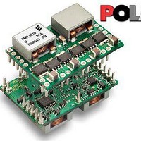
DC/DC Switching Controllers PoL Regul in 4.5-14V O/P 0.7-3.6 50A
Manufacturer
Ericsson Power Modules
Datasheet
1.PMR8210SR.pdf
(21 pages)
Specifications of PMR8210P
Number Of Outputs
1
Output Voltage
3 V to 5.25 V
Output Current
40 A
Output Power
132 W
Switching Frequency
600 KHz
Maximum Operating Temperature
+ 85 C
Minimum Operating Temperature
- 40 C
Lead Free Status / Rohs Status
Lead free / RoHS Compliant


20
21
E
Prepared (also subject responsible if other)
ECOCOLO
Approved
SEC/D (Julia You)
PMR 8000 series PoL Regulator
Input 8 - 14 V, Output up to 40 A / 210 W
Track
Inhibit and UVLO The Inhibit pin is an open-
This is an analog control input
that enables the output
voltage to follow an external
voltage. This pin becomes
active typically 25 ms after
the input voltage has been
applied, and allows direct
control of the output voltage
from 0 V up to the nominal
set-point voltage. Within this
range the module’s output
voltage follows the voltage at
the Track pin on a volt-for-volt
basis. When the control
voltage is raised above this
range, the module regulates
at its set-point voltage. The
features allows the output
voltage to rise simultaneously
with other modules powered
from the same input bus. If
unused, this input should be
connected to V
NOTE: Due to the
undervoltage lockout feature,
the output of the module
cannot follow its own input
voltage during power up. For
more information, see the
related application note.
collector/drain, negative logic
input that is referenced to
GND. Applying a low level
ground signal to this input
disables the module’s output
and turns off the output
voltage. When the Inhibit
control is active, the input
current drawn by the
regulator is significantly
reduced. If the Inhibit pin is
left open-circuit, the module
produces an output whenever
a valid input source is
applied.
This pin is also used for input
undervoltage lockout(UVLO)
programming. Connecting a
resistor from this pin to GND
(pin 13) allows the ON
threshold of the UVLO to be
adjusted higher than the
default value. For more
information, see related
application information.
I
.
Checked
EJANLLI
Ericsson Internal
PRODUCT SPECIFICATION
No.
3/1301-BMR 629 8210 Uen
Date
2009-09-28
22
SmartSync
Technical Specification
EN/LZT 146 411 R1B November 2009
© Ericsson AB
Rev
C
Reference
This input pin sychronizes the
switching frequency of the
module to an external clock
frequency. The SmartSync
feature can be used to
sychronize the switching
frequency of multiple
modules, aiding EMI noise
suppression efforts. The
external synchronization
frequency must be present
before a valid input voltage is
present, or before the release
of inhibit control. If unused,
this pin MUST be connected
to GND. For more
information, please see the
related application note.
8 (9)
16
Related parts for PMR8210P
Image
Part Number
Description
Manufacturer
Datasheet
Request
R

Part Number:
Description:
37.5-150W DC/DC POWER MODULES
Manufacturer:
Ericsson Power Modules
Part Number:
Description:
DC/DC Power Supply Dual-OUT 3.3V/5V 9.6A/6.4A 40W 10-Pin
Manufacturer:
Ericsson Power Modules
Part Number:
Description:
DC/DC Power Supply Single-OUT 3.3V 20A 66W 8-Pin Quarter-Brick
Manufacturer:
Ericsson Power Modules
Datasheet:
Part Number:
Description:
DC/DC Power Supply Single-OUT 1.8V 50A 90W 11-Pin
Manufacturer:
Ericsson Power Modules
Part Number:
Description:
Module DC-DC 1-OUT 1.8V 30A 54W 9-Pin
Manufacturer:
Ericsson Power Modules

Part Number:
Description:
Module DC-DC 1-OUT 1.8V 60A 108W 11-Pin Half-Brick
Manufacturer:
Ericsson Power Modules
Datasheet:

Part Number:
Description:
Module DC-DC 1-OUT 12V 25A 300W 11-Pin Half-Brick
Manufacturer:
Ericsson Power Modules
Part Number:
Description:
Module DC-DC 1-OUT 5V 20A 100W Quarter-Brick
Manufacturer:
Ericsson Power Modules

Part Number:
Description:
Module DC-DC 1-OUT 12V 6A 72W 8-Pin 1/8-Brick
Manufacturer:
Ericsson Power Modules
Datasheet:
Part Number:
Description:
Module DC-DC 1-OUT 5.05V 2A 10W 18-Pin SMD
Manufacturer:
Ericsson Power Modules
Part Number:
Description:
Manufacturer:
Ericsson Power Modules
Datasheet:

Part Number:
Description:
Module DC-DC 1-OUT 5V 60A 300W 11-Pin Half-Brick Tray
Manufacturer:
Ericsson Power Modules
Part Number:
Description:
Module DC-DC 1-OUT 12V 1A 12W 18-Pin
Manufacturer:
Ericsson Power Modules
Datasheet:
Part Number:
Description:
Module DC-DC 2-OUT 12V/-12V 0.25A 6W 18-Pin SMD
Manufacturer:
Ericsson Power Modules
Part Number:
Description:
Module DC-DC 1-OUT 28V 11A 310W 11-Pin Half-Brick Tray
Manufacturer:
Ericsson Power Modules
Datasheet: