PMR8210P Ericsson Power Modules, PMR8210P Datasheet - Page 12
PMR8210P
Manufacturer Part Number
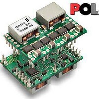
PMR8210P
Description
DC/DC Switching Controllers PoL Regul in 4.5-14V O/P 0.7-3.6 50A
Manufacturer
Ericsson Power Modules
Datasheet
1.PMR8210SR.pdf
(21 pages)
Specifications of PMR8210P
Number Of Outputs
1
Output Voltage
3 V to 5.25 V
Output Current
40 A
Output Power
132 W
Switching Frequency
600 KHz
Maximum Operating Temperature
+ 85 C
Minimum Operating Temperature
- 40 C
Lead Free Status / Rohs Status
Lead free / RoHS Compliant


Over Current Protection (OCP)
The regulators include current limiting circuitry for protection at
continuous overload. The output voltage will decrease towards
zero for output currents in excess of max output current (max
I
of the overload. The load distribution should be designed for
the maximum output short circuit current specified.
Soft-start Power Up
From the moment a valid input voltage is applied, the soft-start
control introduces a short time-delay (typically 5-15 ms) before
allowing the output voltage to rise. The initial rise in input
current when the input voltage first starts to rise is the charge
current drawn by the input capacitors.
Auto-Track™ Function
Auto-Track was designed to simplify the amount of circuitry
required to make the output voltage from each unit power up
and power down in sequence. The sequencing of two or more
supply voltages during power up is a common requirement for
complex mixed-signal applications, that use dual-voltage VLSI
Ics such as DSPs, micro-processors and ASICs.
Notes on Use of Auto-Track™
Smart Sync
Smart Sync is a feature that allows multiple power modules to
be synchronized to a common frequency. When not used, this
pin must be connect to GND. Driving the Smart Sync pins with
an external oscillator set to the desired frequency,
synchronizes all connected modules to the selected requency.
The synchronization frequency can be higher or lower than the
nominal switching frequency of the modules within the range
of 240 kHz to 400 kHz.
Synchronizing modules powered from the same bus
eliminates beat frequencies reflected back to the input supply,
and also reduces EMI filtering requirements. Eliminating the
E
O
1. The Track pin voltage must be allowed to rise above the
module set-point voltage before the module regulates at its
adjusted set-point voltage.
2. The Auto-Track function tracks almost any voltage ramp
during power up, and is compatible with ramp speeds of up to
1 V/ms.
3. The absolute maximum voltage that may be applied to the
Track pin is the input voltage V I .
4. The module cannot follow a voltage at its track control
input until it has completed its soft-start initialization.
This takes about 20 ms from the time that a valid voltage has
been applied to its input. During this period, it is
recommended that the Track pin be held at ground potential.
5. The Auto-Track function is disabled by connecting the
Track pin to the input voltage (V I ). When Auto-Track is
disabled, the output voltage rises according to its softstart
rate after input power has been applied.
6. The Auto-Track pin should never be used to regulate the
module’s output voltage for long-term, steady-state
operation.
Prepared (also subject responsible if other)
ECOCOLO
Approved
SEC/D (Julia You)
PMR 8000 series PoL Regulator
Input 8 - 14 V, Output up to 40 A / 210 W
). The regulator will resume normal operation after removal
Checked
EJANLLI
Ericsson Internal
PRODUCT SPECIFICATION
No.
3/1301-BMR 629 8210 Uen
Date
2009-09-28
low beat frequencies (usually<10kHz) allows the EMI filter to
be designed to attenuate only the synchronization frequency.
Power modules can also be synchronized out of phase to
minimize ripple current and reduce input capacitance
requirements.
The PMR 8210 requires that the external synchronization
frequency be present before a valid input voltage is present or
before release of the inhibit control.
Pre-Bias Startup Capability
A prebias startup condition occurs as a result of an external
voltage being present at the output of a power module prior to
its output becoming active.This often occurs in complex digital
systems when current from another power source is backfed
through a dual-supply logic component, such as FPGA or
ASIC.
The PMR family of regulators incorporate synchronous
rectifiers, but will not sink current during startup, or whenever
the Inhibit pin is held low. However, to ensure satisfactory
operation of this function, certain conditions must be
maintained.
For more inforamtion, please refer to Application Note 205.
Turbo Trans
Turbo Trans
regulator with added external capacitance using a single
external resistor. The benefits of this technology include:
reduced output capacitance, minimized output voltage
deviation following a load transient, and enhanced stability
when using ultra-low ESR output capacitors. The amout of
output capacitance required to meet a target output voltage
deviation, is reduded with Turbo Trans
for a given amout of output capacitance, with Turbo Trans
engaged, the amplitude of the voltage deviation following a
load transient is reduced. Applications requiring tight transient
voltage tolerances and minimized capacitor footprint area
benefit from this technology.
between the +Sense pin (pin 17) and the Turbo Trans
(pin 19), The value of the resistor directly corresponds to the
amount of output capacitance required. For the PMR 8210,
the minimum required capacitance is 1000µF. When using
Turbo Trans
below 10,000 µF×mΩ are required.
To have a better understanding of the required capacitors with
Turbo Trans
a.
b.
c.
As an example, let’s look at a 12-V application requiring a 80
mv deviation during an 20A load transient. A majority of
560µF, 10mΩ output capacitors are used. Use the 12 V, Type
Utilizing Turbo Trans
TypeC
TypeA
TypeB
=
=
=
(5,000
(100
(1
TM
TM
TM
TM
,
000
, capacitors with a capacitance×ESR product
, three types of capacitors are defined as below.
optimizes the transient response of the
Technology
<
Technical Specification
EN/LZT 146 411 R1B November 2009
© Ericsson AB
Rev
C
<
<
capacitanc
capacitanc
capacitanc
TM
requires connecting a resistor, R
e
Reference
e
×
e
ESR
×
×
ESR
ESR
TM
≤
≤
1,000)
≤
activated. Likewise,
5
10,000)
,
000)
TM
4 (9)
12
pin
TT
TM
,
Related parts for PMR8210P
Image
Part Number
Description
Manufacturer
Datasheet
Request
R

Part Number:
Description:
37.5-150W DC/DC POWER MODULES
Manufacturer:
Ericsson Power Modules
Part Number:
Description:
DC/DC Power Supply Dual-OUT 3.3V/5V 9.6A/6.4A 40W 10-Pin
Manufacturer:
Ericsson Power Modules
Part Number:
Description:
DC/DC Power Supply Single-OUT 3.3V 20A 66W 8-Pin Quarter-Brick
Manufacturer:
Ericsson Power Modules
Datasheet:
Part Number:
Description:
DC/DC Power Supply Single-OUT 1.8V 50A 90W 11-Pin
Manufacturer:
Ericsson Power Modules
Part Number:
Description:
Module DC-DC 1-OUT 1.8V 30A 54W 9-Pin
Manufacturer:
Ericsson Power Modules

Part Number:
Description:
Module DC-DC 1-OUT 1.8V 60A 108W 11-Pin Half-Brick
Manufacturer:
Ericsson Power Modules
Datasheet:

Part Number:
Description:
Module DC-DC 1-OUT 12V 25A 300W 11-Pin Half-Brick
Manufacturer:
Ericsson Power Modules
Part Number:
Description:
Module DC-DC 1-OUT 5V 20A 100W Quarter-Brick
Manufacturer:
Ericsson Power Modules

Part Number:
Description:
Module DC-DC 1-OUT 12V 6A 72W 8-Pin 1/8-Brick
Manufacturer:
Ericsson Power Modules
Datasheet:
Part Number:
Description:
Module DC-DC 1-OUT 5.05V 2A 10W 18-Pin SMD
Manufacturer:
Ericsson Power Modules
Part Number:
Description:
Manufacturer:
Ericsson Power Modules
Datasheet:

Part Number:
Description:
Module DC-DC 1-OUT 5V 60A 300W 11-Pin Half-Brick Tray
Manufacturer:
Ericsson Power Modules
Part Number:
Description:
Module DC-DC 1-OUT 12V 1A 12W 18-Pin
Manufacturer:
Ericsson Power Modules
Datasheet:
Part Number:
Description:
Module DC-DC 2-OUT 12V/-12V 0.25A 6W 18-Pin SMD
Manufacturer:
Ericsson Power Modules
Part Number:
Description:
Module DC-DC 1-OUT 28V 11A 310W 11-Pin Half-Brick Tray
Manufacturer:
Ericsson Power Modules
Datasheet: