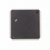
DP83907VF National Semiconductor, DP83907VF Datasheet - Page 48

DP83907VF
Manufacturer Part Number
DP83907VF
Description
IC CONTROLLR AT/LANII TP 160PQFP
Manufacturer
National Semiconductor
Datasheet
1.DP83907VF.pdf
(70 pages)
Specifications of DP83907VF
Controller Type
Network Interface Controller (NIC)
Interface
Twisted Pair
Voltage - Supply
4.75 V ~ 5.25 V
Current - Supply
150mA
Operating Temperature
0°C ~ 70°C
Mounting Type
Surface Mount
Package / Case
160-MQFP, 160-PQFP
Lead Free Status / RoHS Status
Contains lead / RoHS non-compliant
Other names
*DP83907VF
Available stocks
Company
Part Number
Manufacturer
Quantity
Price
Company:
Part Number:
DP83907VF
Manufacturer:
NSC
Quantity:
5 510
6 0 Operation of DP83907
6 5 LOOPBACK DIAGNOSTICS
Three forms of local Ioopback are provided on the
DP83907 The user has the ability to loopback through the
deserializer on the controller through the ENDEC module or
transceiver Because of the half duplex architecture of
the DP83907 loopback testing Is a special mode of op-
eration with the following restrictions
Restrictions During Loopback
The FlFO is split into two halves one half is used for trans-
mission the other for reception Only 8-bit fields can be
fetched from memory so two tests are required for 16-bit
systems to verify integrity of the entire data path During
loopback the maximum latency to obtain access to the buff-
er memory is 2 0 s Systems that wish to use the loopback
test yet do not meet this latency can limit the loopback
packet to 7 bytes without experiencing underflow Only the
last 8 bytes of the loopback packet are retained in the FlFO
The last 8 bytes can be read through the FIFO register
which will advance through the FIFO to allow reading the
receive packet sequentially
When in word-wide mode with Byte Order Select set the
loopback packet must be assembled in the even byte loca-
tions as shown below (The loopback only operated with
byte wide transfers )
When in word-wide mode with Byte Order Select low the
following format must be used for the loopback packet
Note When using loopback in word mode 2n bytes must be programmed in
WTS
Destination Address
WTS
the TBCR0 1 When n
or odd location
Source Address
e
e
LS Byte (D8–D15)
MS Byte (D8–D15)
Length
Data
CRC
1
1
Destination
Source
Length
Data
CRS
BOS
BOS
e
actual number of bytes assembled in even
e
e
1
0
Controller if CRC
e
e
Appended by DP8307
6 bytes Station Physical
6 bytes Station Physical
e
46 to 1500 bytes
Address
Address
2 bytes
MS Byte (D0–D7)
LS Byte (D0–D7)
Destination
(Continued)
(DCR Bits)
(DCR Bits)
Source
Length
e
Data
CRS
0 in TCR
48
To initiate a loopback the user first assembles the loopback
packet then selects the type of loopback using the Transmit
Configuration register bits LB0 LB1 The transmit configura-
tion register must also be set to enable or disable CRC gen-
eration during transmission The user then issues a normal
transmit command to send the packet During loopback the
receiver checks for an address match and if CRC bit in the
TCR is set the receiver will also check the CRC The last 8
bytes of the loopback packet are buffered and can read out
of the FlFO using FlFO read port
Loopback Modes
MODE1 Loopback Through the DP83907 Controller Mod-
ule (LB1
DP83907 Module’s serializer is connected to the deserializ-
er
MODE 2 Loopback Through the ENDEC Module (LB1
LB0
SNI the DP83907 provides a control (LPBK) that forces the
ENDEC module to loopback all signals
MODE 3 Loopback to the external coax interface or twisted
pair interface module (LB1
Packets can be transmitted to the cable in loopback mode
to check all of the transmit and receive paths and the cable
itself If in twisted pair mode there is a link fail the transmit-
ter will be disabled which could give misleading results in
Mode 3 The link integrity should be checked by reading
Configuration Register B before this test
Reading the Loopback Packet
The last eight bytes of a received packet can be examined
by 8 consecutive reads of the FlFO register The FIFO point-
er is increment after the rising edge of the CPU’s read
strobe by internally synchronizing and advancing the point-
er This may take up to four bus clock cycles if the pointer
has not been incremented by the time the CPU reads the
FIFO register again the DP83907 will insert wait states
Note The FIFO may only be read during Loopback Reading the FIFO at
Alignment of the Received Packet In the FIFO
Reception of the packet in the FIFO begins at location zero
after the FIFO pointer reaches the last location in the FlFO
the pointer wraps to the top of the FlFO overwriting the
previously received data This process continued until the
last byte is received The DP83907 then appends the re-
ceived byte count in the next two locations of the FIFO The
contents of the Upper Byte Count are also copied to the
next FlFO location The number of bytes used in the loop-
back packet determined the alignment of the packet in the
FlFO The alignment for a 64-byte packet is shown below
Location
FIFO
e
any other time will cause the DP83907 to malfunction
0
1
2
3
4
5
6
7
0) If the loopback is to be performed through the
e
0 LB0
Lower Byte Count
Upper Byte Count
Upper Byte Count
FIFO Contents
Last Byte
CRC1
CRC2
CRC3
CRC4
e
1) If this loopback is used The
e
1 LB0
e
1)
Second Byte Read
First Byte Read
Last Byte Read
e
1


