KSZ8721B Micrel Inc, KSZ8721B Datasheet - Page 13
KSZ8721B
Manufacturer Part Number
KSZ8721B
Description
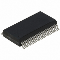
IC TXRX PHY 10/100 2.5V 48-SSOP
Manufacturer
Micrel Inc
Type
Transceiverr
Specifications of KSZ8721B
Number Of Drivers/receivers
1/1
Protocol
MII, RMII
Voltage - Supply
2.375 V ~ 2.625 V
Mounting Type
Surface Mount
Package / Case
48-SSOP
Data Rate
100Mbps
Supply Voltage Range
2.375V To 2.625V
Logic Case Style
SSOP
No. Of Pins
48
Operating Temperature Range
0°C To +70°C
Msl
MSL 2 - 1 Year
Ic Function
Transceiver IC
Termination Type
SMD
Lead Free Status / RoHS Status
Lead free / RoHS Compliant
For Use With
576-1627 - BOARD EVALUATION FOR KSZ8721BMC576-1626 - BOARD EVALUATION FOR KSZ8721BL
Lead Free Status / RoHS Status
Compliant, Lead free / RoHS Compliant
Other names
576-1026-5
576-1510-5
576-1510-5
KSZ8721B
576-1510-5
576-1510-5
KSZ8721B
Available stocks
Company
Part Number
Manufacturer
Quantity
Price

Part Number:
KSZ8721B
Manufacturer:
MICREL/麦瑞
Quantity:
20 000
Company:
Part Number:
KSZ8721B TR
Manufacturer:
MICREL
Quantity:
5 000
Company:
Part Number:
KSZ8721B-TR
Manufacturer:
Micrel
Quantity:
3 283
Company:
Part Number:
KSZ8721BL
Manufacturer:
MICREL
Quantity:
127
Part Number:
KSZ8721BL
Manufacturer:
MIC
Quantity:
20 000
Company:
Part Number:
KSZ8721BL TR
Manufacturer:
Renesas
Quantity:
33
Part Number:
KSZ8721BL TR
Manufacturer:
MICREL/麦瑞
Quantity:
20 000
Company:
Part Number:
KSZ8721BL-TR
Manufacturer:
MICREL
Quantity:
814
Part Number:
KSZ8721BL-TR
Manufacturer:
MICREL/麦瑞
Quantity:
20 000
Part Number:
KSZ8721BLA4
Manufacturer:
MICREL/麦瑞
Quantity:
20 000


Collision: Whenever the line state is half-duplex and the transmitter and receiver are active at the same time, the KS8721B/
BT asserts its collision signal, which is asynchronous to any clock.
RMII (Reduced MII) Data Interface
RMII interface specifi es a low pin count (Reduced) Media Independent Interface (RMII) intended for use between Ethernet
PHYs and Switch or Repeater ASICs. It is fully compliant with IEEE 802.3u [2].
This interface has the following characteristics:
RMII Signal Defi nition
Note 1.
Reference Clock (REF_CLK)
REF_CLK is a continuous 50MHz clock that provides the timing reference for CRS_DV, RXD[1:0], TX_EN, TXD[1:0], and
RX_E. REF_CLK is sourced by the MAC or an external source. Switch implementations may choose to provide REF_CLK
as an input or an output depending on whether they provide a REF_CLK output or rely on an external clock distribution
device. Each PHY device shall have an input corresponding to this clock but may use a single clock input for multiple PHYs
implemented on a single IC.
Carrier Sense/Receive Data Valid (CRS_DV)
CRS_DV is asserted asynchronously on detection of carrier due to the criteria relevant to the operating mode. That is, in
10BASE-T mode, when squelch is passed or in 100BASE-X mode when 2 non-contiguous zeroes in 10 bits are detected
carrier is said to be detected.
Loss of carrier shall result in the de-assertion of CRS_DV synchronous to REF_CLK. So long as carrier criteria are being
met, CRS_DV shall remain asserted continuously from the fi rst recovered di-bit of the frame through the fi nal recovered di-
bit and shall be negated prior to the fi rst REF_CLK that follows the fi nal di-bit.
The data on RXD[1:0] is considered valid once CRS_DV is asserted. However, since the assertion of CRS_DV is asynchro-
nous relative to REF_CLK, the data on RXD[1:0] shall be “00” until proper receive signal decoding takes place (see defi nition
of RXD[1:0] behavior).
Receive Data [1:0] (RXD[1:0])
RXD[1:0] shall transition synchronously to REF_CLK. For each clock period in which CRS_DV is asserted, RXD[1:0] transfers
two bits of recovered data from the PHY. In some cases (e.g. before data recovery or during error conditions) a pre-deter-
mined value for RXD[1:0] is transferred instead of recovered data. RXD[1:0] shall be “00” to indicate idle when CRS_DV is
de-asserted. Values of RXD[1:0] other than “00” when CRS_DV is de-asserted are reserved for out-of-band signalling (to
be defi ned). Values other than “00” on RXD[1:0] while CRS_DV is de-asserted shall be ignored by the MAC/repeater. Upon
assertion of CRS_DV, the PHY shall ensure that RXD[1:0]=00 until proper receive decoding takes place.
Transmit Enable (TX_EN)
Transmit Enable TX_EN indicates that the MAC is presenting di-bits on TXD[1:0] on the RMII for trans-mission. TX_EN shall
be asserted synchronously with the fi rst nibble of the preamble and shall remain asserted while all di-bits to be transmitted
are presented to the RMII. TX_EN shall be negated prior to the fi rst REF_CLK following the fi nal di-bit of a frame. TX_EN
shall transition synchronously with respect to REF_CLK.
March 2006
Signal Name
Signal Name
REF_CLK
REF_CLK
REF_CLK
REF_CLK
REF_CLK
REF_CLK
CRS_DV
CRS_DV
CRS_DV
CRS_DV
CRS_DV
RXD[1:0]
RXD[1:0]
RXD[1:0]
RXD[1:0]
RXD[1:0]
TX_EN
TX_EN
TX_EN
TX_EN
TX_EN
TXD[1:0]
TXD[1:0]
TXD[1:0]
TXD[1:0]
TXD[1:0]
RX_ER
RX_ER
RX_ER
RX_ER
RX_ER
• It is capable of supporting 10Mbps and 100Mbps data rates.
• A single clock reference is sourced from the MAC to PHY (or from an external source).
• It provides independent 2-bit wide (di-bit) transmit and receive data paths.
• It uses TTL signal levels, compatible with common digital CMOS ASIC processes.
Unused MII signals, TXD[3:2], TXER need to tie to GND when RMII is using.
Direction
Direction
Direction
(w/ respect to the PHY)
(w/ respect to the PHY)
Input
Input
Input
Input
Input
Input
Output
Output
Output
Output
Output
Output
Output
Output
Output
Output
Input
Input
Input
Input
Input
Input
Input
Input
Input
Input
Output
Output
Output
Output
Output
Direction
Direction
Direction
(w/ respect to the MAC)
(w/ respect to the MAC)
Input or Output
Input or Output
Input or Output
Input or Output
Input or Output
Input or Output
Input
Input
Input
Input
Input
Input
Input
Input
Input
Input
Output
Output
Output
Output
Output
Output
Output
Output
Output
Output
Input (Not Required)
Input (Not Required)
Input (Not Required)
Input (Not Required)
Input (Not Required)
13
Use
Use
Synchronous clock reference for receive, transmit and
Synchronous clock reference for receive, transmit and
Synchronous clock reference for receive, transmit and
Synchronous clock reference for receive, transmit and
Synchronous clock reference for receive, transmit and
Synchronous clock reference for receive, transmit and
control interface
control interface
control interface
control interface
control interface
Carrier Sense/Receive Data Valid
Carrier Sense/Receive Data Valid
Carrier Sense/Receive Data Valid
Carrier Sense/Receive Data Valid
Carrier Sense/Receive Data Valid
Receive Data
Receive Data
Receive Data
Receive Data
Receive Data
Transit Enable
Transit Enable
Transit Enable
Transit Enable
Transit Enable
Transit Data
Transit Data
Transit Data
Transit Data
Transit Data
Receive Error
Receive Error
Receive Error
Receive Error
Receive Error
M9999-030106
Related parts for KSZ8721B
Image
Part Number
Description
Manufacturer
Datasheet
Request
R

Part Number:
Description:
Manufacturer:
Micrel Inc
Datasheet:
Part Number:
Description:
Manufacturer:
Micrel Inc
Datasheet:
Part Number:
Description:
Manufacturer:
Micrel Inc
Datasheet:
Part Number:
Description:
Manufacturer:
Micrel Inc
Datasheet:
Part Number:
Description:
Manufacturer:
Micrel Inc
Datasheet:
Part Number:
Description:
Manufacturer:
Micrel Inc
Datasheet:
Part Number:
Description:
Manufacturer:
Micrel Inc
Datasheet:
Part Number:
Description:
Manufacturer:
Micrel Inc
Datasheet:
Part Number:
Description:
Manufacturer:
Micrel Inc
Datasheet:
Part Number:
Description:
Manufacturer:
Micrel Inc
Datasheet:
Part Number:
Description:
Manufacturer:
Micrel Inc
Datasheet:
Part Number:
Description:
Manufacturer:
Micrel Inc
Datasheet:
Part Number:
Description:
Manufacturer:
Micrel Inc
Datasheet:
Part Number:
Description:
Manufacturer:
Micrel Inc
Datasheet: