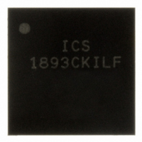
ICS1893CKILF IDT, Integrated Device Technology Inc, ICS1893CKILF Datasheet - Page 35

ICS1893CKILF
Manufacturer Part Number
ICS1893CKILF
Description
PHYCEIVER LOW PWR 3.3V 56-MLF2
Manufacturer
IDT, Integrated Device Technology Inc
Series
PHYceiver™r
Type
PHY Transceiverr
Datasheet
1.ICS1893CFLFT.pdf
(127 pages)
Specifications of ICS1893CKILF
Protocol
MII
Voltage - Supply
3.14 V ~ 3.47 V
Mounting Type
Surface Mount
Package / Case
56-VQFN
Lead Free Status / RoHS Status
Lead free / RoHS Compliant
Number Of Drivers/receivers
-
Lead Free Status / RoHS Status
Compliant, Lead free / RoHS Compliant
Other names
1893CKILF
800-1023
800-1023
Available stocks
Company
Part Number
Manufacturer
Quantity
Price
Company:
Part Number:
ICS1893CKILF
Manufacturer:
IDT
Quantity:
206
Company:
Part Number:
ICS1893CKILFT
Manufacturer:
ST
Quantity:
785
Part Number:
ICS1893CKILFT
Manufacturer:
ICS
Quantity:
20 000
6.5.2 10Base-T Operation: Clock Synthesis
6.5.3 10Base-T Operation: Clock Recovery
6.5.4 10Base-T Operation: Idle
6.5.5 10Base-T Operation: Link Monitor
ICS1893CF, Rev. K, 05/13/10
During 10Base-T data reception, a Manchester Decoder translates the serial bit stream obtained from the
Twisted-Pair Receiver (MDI) into an NRZ bit stream. The Manchester Decoder then passes the data to the
MAC Interface in parallel format.
Manchester-encoded signals have the following advantages:
•
•
The primary disadvantage in using Manchester-encoded signals is that it doubles the data rate, making it
operationally prohibitive for 100-MHz operations.
The ICS1893CF synthesizes the clocks required for synchronizing data transmission. In 10Base-T mode,
the MAC Interface provides a 10M MII (Media Independent Interface):
•
The ICS1893CF recovers its receive clock from the Manchester-encoded data stream obtained from its
Twisted-Pair Receiver using a phase-locked loop (PLL). The ICS1893CF then uses this recovered clock for
synchronizing data transmission between itself and the MAC. Receive-clock PLL acquisitions begin with
reception of the MAC Frame Preamble and continue as long as the ICS1893CF is receiving data.
An ICS1893CF transmits Normal Link Pulses on its MDI in the absence of data. During this time the link is
Idle, and the ICS1893CF periodically transmits link pulses at a rate of one link pulse every 16 ms in
compliance with the ISO/IEC 8802-3 standard. In 10Base-T mode, the ICS1893CF continues transmitting link
pulses even while receiving data. This situation does not generate a Collision Detect signal (COL) because
link pulses indicate an idle state for a link.
When an ICS1893CF is in 10Base-T mode, its Link Monitor Function observes the data received by the
10Base-T Twisted-Pair Receiver to determine the link status. The results of this continual monitoring are
stored in the Link Status bit. The Station Management entity (STA) can access the Link Status bit in either
the Status Register (bit 1.2) or the QuickPoll Detailed Status Register (bit 17.0).
When the Link Status bit is:
•
•
The ICS1893CF Link Status bit is a latching low (LL) bit. (For more information on latching high and latching
low bits, see
The criteria used by the Link Monitor Function to declare a link either valid or invalid depends upon these
factors: the present state of the link, whether its Smart Squelch function is enabled, and the incoming data.
Every bit period has an encoded clock.
The split-phase nature of the signal always provides a zero DC level regardless of the data (that is, there
is no baseline wander phenomenon).
10M MII interface, the ICS1893CF synthesizes a 2.5-MHz clock for nibble-wide transactions
Zero, either a valid link is not established or the link is momentarily dropped since either the last read of
the Link Status bit or the last reset of the ICS1893CF.
One, a valid link is established.
ICS1893CF Data Sheet Rev. J - Release
Section 7.1.4.1, “Latching High Bits”
Copyright © 2009, Integrated Device Technology, Inc.
All rights reserved.
35
and
Section 7.1.4.2, “Latching Low
Chapter 6 Functional Blocks
Bits”.)
May, 2010


