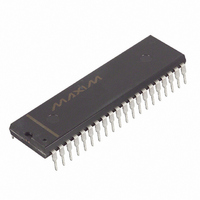
DS2181A+ Maxim Integrated Products, DS2181A+ Datasheet - Page 6

DS2181A+
Manufacturer Part Number
DS2181A+
Description
IC TXRX CEPT PRIMARY RATE 40-DIP
Manufacturer
Maxim Integrated Products
Type
Transceiverr
Datasheet
1.DS2181A.pdf
(32 pages)
Specifications of DS2181A+
Number Of Drivers/receivers
1/1
Protocol
CEPT
Voltage - Supply
4.5 V ~ 5.5 V
Mounting Type
Through Hole
Package / Case
40-DIP (0.600", 15.24mm)
Logic Type
CMOS
Supply Voltage (max)
5.5 V
Supply Voltage (min)
4.5 V
Maximum Operating Temperature
+ 70 C
Mounting Style
Through Hole
High Level Output Current
- 1 mA
Interface
DMA, CPI
Low Level Output Current
4 mA
Minimum Operating Temperature
0 C
Output Current
4 mA
Supply Current
5 mA
Supply Voltage Range
4.5V To 5.5V
Logic Case Style
LCC
No. Of Pins
44
Operating Temperature Range
0°C To +70°C
Termination Type
SMD
Transceiver Type
Network
Driver Case Style
LCC
Rohs Compliant
Yes
Filter Terminals
SMD
Interface Type
Serial
Lead Free Status / RoHS Status
Lead free / RoHS Compliant
REGISTER SUMMARY Table 5
NOTES:
1. Transmit or receive side register.
2. RSR is a read only register; all other registers are read/write.
3. Reserved bit locations must be programmed to 0.
SERIAL PORT INTERFACE
Pins 14 through 18 of the DS2181A serve as a microprocessor/ microcontroller-compatible serial port.
Fourteen on-chip registers allow the user to update operational characteristics and monitor device status
via a host controller, minimizing hardware interfaces.
Port read/write timing is unrelated to the chip transmit and receive timing, allowing asynchronous reads
and/ or writes by the host. The timing set is identical to that of 8051-type microcontrollers operating in
serial port mode 0. For proper operation of the port and the transmit and receive registers, the user should
provide TCLK and RCLK as well as SCLK.
REGISTE
BVCR
RIMR
CECR
FECR
TINR
TIR1
TIR2
TIR3
TIR4
RCR
CCR
TCR
TXR
RSR
R
ADDRE
0000
0001
0010
0011
0100
0101
0110
0111
1000
1001
1010
1011
1100
1101
SS
T/R
T/R
R
R
R
R
R
R
T
T
T
T
2
1
Receive Interrupt Mask Register. Allows masking of alarm
generated interrupts.
Receive Status Register. Reports all receive alarm conditions.
Bipolar Violation Count Register. 8-bit presettable counter
which records individual bipolar violations.
CRC4 Error Count Register. 8-bit presettable counter which
records individual errors.
Frame Error Count Register. 8-bit presettable counter which
logs individual errors in the received frame alignment signal.
Receive Control Register. Establishes receive side operating
characteristics.
Common Control Register. Establishes additional operating
characteristics for transmit and receive sides.
Transmit Control Register. Establishes transmit side operation
characteristics.
Transmit Idle Registers. Designates which outgoing timeslots are
to be substituted with idle code.
Transmit International and National Register. When enabled via
the TCR, contents inserted into the outgoing national and/or
international bit positions.
Transmit Extra Register. When enabled via the TCR, contents
inserted into the out going extra bit positions.
6 of 32
DESCRIPTION/FUNCTION
DS2181A


