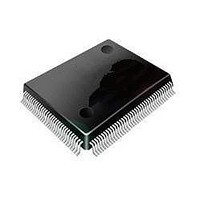
STM32L152VBT6 STMicroelectronics, STM32L152VBT6 Datasheet - Page 20

STM32L152VBT6
Manufacturer Part Number
STM32L152VBT6
Description
16/32-BITS MICROS
Manufacturer
STMicroelectronics
Series
STM32r
Datasheet
1.STM32L152-EVAL.pdf
(107 pages)
Specifications of STM32L152VBT6
Processor Series
STM32L152
Core
ARM Cortex M3
Data Bus Width
32 bit
Program Memory Type
Flash
Program Memory Size
128 KB
Data Ram Size
16 KB
Interface Type
I2C, SPI, USART
Maximum Clock Frequency
32 MHz
Number Of Programmable I/os
80
Number Of Timers
6
Operating Supply Voltage
1.8 V to 3.6 V
Maximum Operating Temperature
+ 85 C
Mounting Style
SMD/SMT
Package / Case
LQFP-100
Core Processor
ARM® Cortex-M3™
Core Size
32-Bit
Speed
32MHz
Connectivity
I²C, IrDA, LIN, SPI, UART/USART, USB
Peripherals
Brown-out Detect/Reset, DMA, I²S, LCD, POR, PWM, WDT
Number Of I /o
83
Eeprom Size
4K x 8
Ram Size
16K x 8
Voltage - Supply (vcc/vdd)
1.65 V ~ 3.6 V
Data Converters
A/D 24x12b; D/A 2x12b
Oscillator Type
Internal
Operating Temperature
-40°C ~ 85°C
Lead Free Status / Rohs Status
Details
Available stocks
Company
Part Number
Manufacturer
Quantity
Price
Company:
Part Number:
STM32L152VBT6
Manufacturer:
STMicroelectronics
Quantity:
10 000
Part Number:
STM32L152VBT6
Manufacturer:
ST
Quantity:
20 000
Company:
Part Number:
STM32L152VBT6TR
Manufacturer:
STMicroelectronics
Quantity:
10 000
Functional overview
3.10
3.11
20/107
ADC (analog-to-digital converter)
A 12-bit analog-to-digital converters is embedded into STM32L15xxx devices with up to 24
external channels, performing conversions in single-shot or scan mode. In scan mode,
automatic conversion is performed on a selected group of analog inputs.
The ADC can be served by the DMA controller.
An analog watchdog feature allows very precise monitoring of the converted voltage of one,
some or all selected channels. An interrupt is generated when the converted voltage is
outside the programmed thresholds.
The events generated by the general-purpose timers (TIMx) can be internally connected to
the ADC start trigger and injection trigger, to allow the application to synchronize A/D
conversions and timers.
The ADC includes a specific low power mode. The converter is able to operate at maximum
speed even if the CPU is operating at a very low frequency and has an auto-shutdown
function. The ADC’s runtime and analog front-end current consumption are thus minimized
whatever the MCU operating mode.
Temperature sensor
The temperature sensor has to generate a voltage that varies linearly with temperature. The
conversion range is between 1.8 V < V
connected to the ADC_IN16 input channel.
DAC (digital-to-analog converter)
The two 12-bit buffered DAC channels can be used to convert two digital signals into two
analog voltage signal outputs. The chosen design structure is composed of integrated
resistor strings and an amplifier in non-inverting configuration.
This dual digital Interface supports the following features:
●
●
●
●
●
●
●
●
●
Eight DAC trigger inputs are used in the STM32L15xxx. The DAC channels are triggered
through the timer update outputs that are also connected to different DMA channels.
two DAC converters: one for each output channel
left or right data alignment in 12-bit mode
synchronized update capability
noise-wave generation
triangular-wave generation
dual DAC channels’ independent or simultaneous conversions
DMA capability for each channel (including the underrun interrupt)
external triggers for conversion
input reference voltage V
REF+
Doc ID 17659 Rev 4
DDA
< 3.6 V. The temperature sensor is internally
STM32L151xx, STM32L152xx


