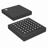
DS21348G Maxim Integrated Products, DS21348G Datasheet - Page 47

DS21348G
Manufacturer Part Number
DS21348G
Description
IC LIU T1/E1/J1 3.3V 49-BGA
Manufacturer
Maxim Integrated Products
Type
Line Interface Units (LIUs)r
Datasheet
1.DS21348G.pdf
(76 pages)
Specifications of DS21348G
Number Of Drivers/receivers
1/1
Protocol
T1/E1/J1
Voltage - Supply
3.135 V ~ 3.465 V
Mounting Type
Surface Mount
Package / Case
49-CSBGA
Lead Free Status / RoHS Status
Contains lead / RoHS non-compliant
Available stocks
Company
Part Number
Manufacturer
Quantity
Price
Part Number:
DS21348G
Manufacturer:
NXP/恩智浦
Quantity:
20 000
Part Number:
DS21348G+
Manufacturer:
MAXIM/美信
Quantity:
20 000
Company:
Part Number:
DS21348GN-C01
Manufacturer:
Maxim Integrated
Quantity:
10 000
6.3 PRBS Generation and Detection
Setting TPRBSE (CCR3.4) = 1 enables the DS21348 to transmit a 2
Random Bit Sequence (PRBS) depending on the ETS bit setting in CCR1.7. The receive-side of the
DS21348 will always search for these PRBS patterns independent of CCR3.4. The PRBS Bit Error
Output (PBEO) will remain high until the receiver has synchronized to one of the two patterns (64 bits
received without an error) at which time PBEO will go low and the PRBSD bit in the Status Register
(SR) will be set. Once synchronized, any bit errors received will cause a positive going pulse at PBEO,
synchronous with RCLK. This output can be used with external circuitry to keep track of bit error rates
during the PRBS testing. Setting CCR6.0 (ECRS) = 1 will allow the PRBS errors to be accumulated in
the 16-bit counter in registers ECR1 and ECR2. The PRBS synchronizer will remain in sync until it
experiences 6 bit errors or more within a 64-bit span. Both PRBS patterns comply with the ITU-T O.151
specifications.
6.4 Error Counter
Error Count Register 1 (ECR1) is the most significant word and ECR2 is the least significant word of a
user selectable 16-bit counter that records incoming errors including BiPolar Violations (BPV), Code
Violations (CV), Excessive Zero violations (EXZ) and/or PRBS Errors. See
Figure 1-2
Table 6-3. Definition of Received Errors
ERROR
PRBS
BPV
EXZ
EXZ
CV
for details.
E1 OR T1
E1/T1
E1/T1
E1
E1
T1
Two consecutive marks with the same polarity. Will ignore BPVs due to
HDB3 and B8ZS zero suppression when CCR2.3 = 0. Typically used with
AMI coding (CCR2.3 = 1). ITU-T O.161.
When HDB3 is enabled (CCR2.3 = 0) and the receiver detects two
consecutive BPVs with the same polarity. ITU-T O.161.
When four or more consecutive zeros are detected.
When receiving AMI coded signals (CCR2.3 = 1), detection of 16 or more
zeros or a BPV. ANSI T1.403 1999.
When receiving B8ZS coded signals (CCR2.3 = 0), detection of 8 or more
zeros or a BPV. ANSI T1.403 1999.
A bit error in a received PRBS pattern. See Section
O.151.
DEFINITION OF RECEIVED ERRORS
47 of 76
15
- 1 (E1) or a 2
Table 6-3
6.3
for details. ITU-T
20
and
- 1 (T1) Pseudo-
Table 6-4
and


