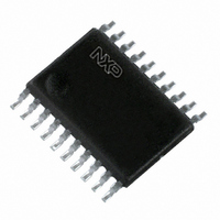
74LVC1284PW,112 NXP Semiconductors, 74LVC1284PW,112 Datasheet - Page 4

74LVC1284PW,112
Manufacturer Part Number
74LVC1284PW,112
Description
IC PRINT INTFC TXRX/BUFF 20TSSOP
Manufacturer
NXP Semiconductors
Series
74LVCr
Type
Transceiverr
Datasheet
1.74LVC1284PW118.pdf
(10 pages)
Specifications of 74LVC1284PW,112
Number Of Drivers/receivers
4/4
Protocol
IEEE 1284
Voltage - Supply
3 V ~ 3.6 V
Mounting Type
Surface Mount
Package / Case
20-TSSOP
Number Of Transmitters
1
Number Of Receivers
1
Power Supply Requirement
Single
Package Type
TSSOP
Operating Temperature Classification
Commercial
Mounting
Surface Mount
Pin Count
20
Operating Temperature (max)
70C
Operating Temperature (min)
0C
Dual Supply Voltage (typ)
Not RequiredV
Dual Supply Voltage (max)
Not RequiredV
Dual Supply Voltage (min)
Not RequiredV
Lead Free Status / RoHS Status
Lead free / RoHS Compliant
Other names
568-2999-5
935213670112
935213670112
Philips Semiconductors
DC ELECTRICAL CHARACTERISTICS
AC CHARACTERISTICS
GND = 0V, t
1995 Nov 10
SYMBOL
SYMBOL
I
SR
t
t
t
t
t
t
t
t
t
t
t
t
t
t
t
t
I
I
IH
PLH
PHL
PLH
PHL
PZH
PHZ
PZL
PLZ
PZH
PZL
PHZ
PLZ
PZH
PZL
PHZ
PLZ
3.3V Parallel printer interface transceiver/buffer
IHZ
IL
V
I
V
I
I
V
V
V
+I
+I
V
R
OFF
OZH
I
OZL
HYS
CC
OH
I
OL
IH
/I
IL
D
I
OZH
OZL
ILZ
R
High level
High-level
output voltage
out ut voltage
Low-level
Low level
output voltage
High-level input voltage
Low-level input voltage
Input Hysteresis
B/Y side Output
Impedance
Input leakage current
(A5-A7 DIR, HD)
Input current for common
I/O pins
B/Y Side Power-off
leakage current
3-State output High
current Yn
3-State output Low
current Yn
current (A1 – A4, Bn)
current (A1 – A4, Bn)
Quiescent Supply
Current
B-Side Slew Rate
Propagation delay
A toY or A to B
Propagation delay
B to A
Output enable/disable time to/from High level
HD to Y or HD to B
Output enable/disable time to/from Low level
A to Y or A to B
Output enable time
from DIR to B
Output disable time
from DIR to B
Output enable time
from DIR to A
Output disable
from DIR to A
= t
F
= 3.0ns, C
PARAMETER
L
PARAMETER
Bn or Yn V
Bn or Yn V
= 50pF, R
An
An
An
L
V
V
V
V
V
V
V
V
See Figure 2
V
Not for I/O pins
V
V
V
V
V
V
V
= 500
CC
CC
CC
CC
I
CC
CC
CC
CC
CC
CC
CC
CC
CC
CC
CC
CC
CC
= V
= Min to Max; I
= 3.0V; I
= 3.0V; I
= Min to Max; I
= 3.0V; I
= 3.0V; I
= Min to Max
= Min to Max
= 3.3V
= 3.6V; V
= 3.6V;V
= 0.0V; V
= 3.6V; V
= 3.6V; V
= 3.6V; V
= 3.6V; V
= 3.6V; I
IL
or V
TEST CONDITIONS
IH
OH
OH
OL
OL
O
I
O
O
O
O
I/O
I/O
= 5.5V or GND
= 0; V
= V
= 0 to 5.5V
= V
= GND; V
= 4mA; V
= –14mA; V
= –4mA
= 14mA
= V
= GND
CC
CC
OH
OL
CC
I
WAVEFORM
; V
= GND or V
= 50 A;
or GND;
= –50 A
I
I
I
= V
= V
= V
4
5
1
2
2
2
2
2
2
I
= V
IL
4
IL
IL
or V
or V
IL
or V
CC
or V
IH
IH
IH
IH
0.05
MIN
6.0
6.0
1.5
1.5
4.0
2.0
5.0
1.5
8.0
8.0
5.0
6.0
3.5
4.0
2.5
2.5
V
CC
MIN
2.4
2.2
2.0
38
T
–0.2
V
amb
CC
T
amb
TYP
12.6
12.4
12.0
12.7
12.3
12.7
0.2
5.5
5.6
6.5
5.0
8.9
9.1
6.9
8.6
3.7
3.7
= 3.3V
= 25 C
"0.1
TYP
= 25 C
V
2.4
0.4
45
CC
5
LIMITS
MAX
0.35
18.0
18.0
16.0
16.3
18.0
18.0
12.5
12.0
13.0
14.0
7.9
7.6
9.1
7.1
5.5
5.0
MAX
"15
LIMITS
0.2
0.4
0.8
0.8
53
–5
–5
10
1.0
10
5
5
T
V
T
amb
V
CC
amb
0.05
MIN
CC
MIN
2.4
2.1
2.0
0.3
5.0
5.0
1.5
1.5
4.0
2.0
5.0
1.5
4.0
4.0
2.0
2.0
3.0
3.0
2.0
2.0
35
–0.2
= 0 C to +70 C
= Min to Max
= 0 to + 70 C
74LVC1284
Product specification
MAX
MAX
19.5
20.0
20.0
20.0
20.0
20.0
14.5
14.0
14.5
16.0
11.0
–20
–25
0.2
0.4
0.9
0.8
0.4
9.5
9.0
9.0
6.0
5.5
55
100
20
25
50
5.0
UNIT
UNIT
V/ns
ns
ns
ns
ns
ns
ns
ns
ns
V
V
V
V
V
V
V
A
A
A
A
A
A
A
A


