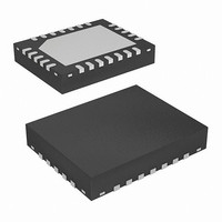
EL1503ACL Intersil, EL1503ACL Datasheet - Page 15

EL1503ACL
Manufacturer Part Number
EL1503ACL
Description
IC INTERFACE ADSL/HDSL2 24-QFN
Manufacturer
Intersil
Type
Driverr
Datasheet
1.EL1503ACL.pdf
(17 pages)
Specifications of EL1503ACL
Number Of Drivers/receivers
2/0
Protocol
DSL
Voltage - Supply
5 V ~ 12 V
Mounting Type
Surface Mount
Package / Case
24-VQFN Exposed Pad, 24-HVQFN, 24-SQFN, 24-DHVQFN
Lead Free Status / RoHS Status
Contains lead / RoHS non-compliant
Available stocks
Company
Part Number
Manufacturer
Quantity
Price
Part Number:
EL1503ACL
Manufacturer:
EL
Quantity:
20 000
Power Control Function
The EL1503A contains two forms of power control operation.
Two digital inputs, C
supply current of the EL1503A drive amplifiers. As the
supply current is reduced, the EL1503A will start to exhibit
slightly higher levels of distortion and the frequency
response will be limited. The 4 power modes of the EL1503A
are set up as shown in the table 2.
Intersil products are sold by description only. Intersil Corporation reserves the right to make changes in circuit design, software and/or specifications at any time without
notice. Accordingly, the reader is cautioned to verify that data sheets are current before placing orders. Information furnished by Intersil is believed to be accurate and
reliable. However, no responsibility is assumed by Intersil or its subsidiaries for its use; nor for any infringements of patents or other rights of third parties which may result
from its use. No license is granted by implication or otherwise under any patent or patent rights of Intersil or its subsidiaries.
C
0
0
1
1
1
TABLE 2. POWER MODES of the EL1503A
C
0
1
0
1
All Intersil U.S. products are manufactured, assembled and tested utilizing ISO9000 quality systems.
0
Intersil Corporation’s quality certifications can be viewed at www.intersil.com/design/quality
0
I
2/3 I
1/3 I
Power down
S
and C
For information regarding Intersil Corporation and its products, see www.intersil.com
full power mode (CO or CP)
S
S
power mode (CO or CP)
terminate only mode
1
15
, can be used to control the
OPERATION
EL1503A
I
Another method for controlling the power consumption of the
EL1503A is to connect a resistor from the I
When this pin is grounded (the normal state), the supply
current per channel is as per the specifications table on page
3. When a resistor is inserted, the supply current is scaled
according to the “I
Performance Curves section.
Both methods of power control can be used simultaneously.
In this case, positive and negative supply currents (per amp)
are given by the equations below:
I
+
S
+
S
+
(
-
(
C
C
=
=
0
0
×
0
1mA
×
1 3 )
+
1 3 )
⁄
(
⁄
C
+
1
×
(
×
×
C
------------------------------------------ -
1 (
------------------------------------------ -
1 (
2 3 )
1
⁄
×
+
+
12.5mA
S
2 3 )
12.5mA
R
R
⁄
SET
×
vs R
SET
------------------------------------------ -
1 (
×
+
÷
SET
÷
------------------------------------------ -
1 (
12.5mA
1k )
R
1k )
SET
+
” graphs on page 10 in the
12.5mA
R
SET
÷
1k )
÷
1k )
ADJ
pin to ground.
March 26, 2007
FN7039.2


