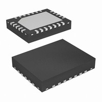
EL1503ACL Intersil, EL1503ACL Datasheet - Page 3

EL1503ACL
Manufacturer Part Number
EL1503ACL
Description
IC INTERFACE ADSL/HDSL2 24-QFN
Manufacturer
Intersil
Type
Driverr
Datasheet
1.EL1503ACL.pdf
(17 pages)
Specifications of EL1503ACL
Number Of Drivers/receivers
2/0
Protocol
DSL
Voltage - Supply
5 V ~ 12 V
Mounting Type
Surface Mount
Package / Case
24-VQFN Exposed Pad, 24-HVQFN, 24-SQFN, 24-DHVQFN
Lead Free Status / RoHS Status
Contains lead / RoHS non-compliant
Available stocks
Company
Part Number
Manufacturer
Quantity
Price
Part Number:
EL1503ACL
Manufacturer:
EL
Quantity:
20 000
s
Absolute Maximum Ratings
V
V
V
Input C
Driver V
CAUTION: Stresses above those listed in “Absolute Maximum Ratings” may cause permanent damage to the device. This is a stress only rating and operation of the
device at these or any other conditions above those indicated in the operational sections of this specification is not implied.
IMPORTANT NOTE: All parameters having Min/Max specifications are guaranteed. Typical values are for information purposes only. Unless otherwise noted, all tests
are at the specified temperature and are pulsed tests, therefore: T
Electrical Specifications
SUPPLY CHARACTERISTICS
I
I
I
I
I
I
I
I
I
INPUT CHARACTERISTICS
V
ΔV
I
I
ΔI
R
e
i
V
V
I
I
I
OUTPUT CHARACTERISTICS
V
I
I
N
S
S
S
S
S
S
S
S
S
S
S
GND
B
B
IH1
IH0
IL
OL
OUT
N
PARAMETER
OS
IH
IL
OUT
OL
+
-
+
-
+
-
+
-
+
-
B
+ to V
+ Voltage to Ground . . . . . . . . . . . . . . . . . . . . . . . . -0.3V to +28V
- Voltage to Ground . . . . . . . . . . . . . . . . . . . . . . . . . . -28V to 0.3V
(Full Power)
(Low Power)
(Terminate)
(Power Down)
OS
(Full Power)
(Low Power)
(Terminate)
(Power Down)
-
0
IN
/C
S
- Supply Voltage. . . . . . . . . . . . . . . . . . . . . . . . . . . . . .28V
+ Voltage . . . . . . . . . . . . . . . . . . . . . . . . . . . . . V
1
to Ground . . . . . . . . . . . . . . . . . . . . . . . . . . -0.3V to +7V
Positive Supply Current per Amplifier
Negative Supply Current per Amplifier
Positive Supply Current per Amplifier
Negative Supply Current per Amplifier
Positive Supply Current per Amplifier
Negative Supply Current per Amplifier
Positive Supply Current per Amplifier
Negative Supply Current per Amplifier
GND Supply Current per Amplifier
Input Offset Voltage
V
Non-Inverting Input Bias Current
Inverting Input Bias Current
I
Transimpedance
Input Noise Voltage
-Input Noise Current
Input High Voltage
Input Low Voltage
Input High Current for C
Input High Current for C
Input Low Current for C
Loaded Output Swing
Linear Output Current
Output Current
B
OS
- Mismatch
Mismatch
DESCRIPTION
3
V
S
(T
= ±12V, R
A
= +25°C)
1
1
0
or C
0
F
= 1.5kΩ, R
J
S
= T
- to V
L
C
All outputs at 0V, C
All outputs at 0V, C
All outputs at 0V, C
All outputs at 0V, C
All outputs at 0V, C
All outputs at 0V, C
All outputs at 0V, C
All outputs at 0V, C
All outputs at 0V
C
C
C
C
C
R
R
A
THD = --60dBc
V
= 65Ω, I
= T
V
OUT
0
0
1
0
1
L
L
S
EL1503A
= 5, R
& C
& C
= 5V
= 5V
= 0V, C
= 65Ω
= 22Ω
A
+
= 1V, R
1
1
ADJ
inputs
inputs
L
0
= 10Ω, f = 100kHz,
= 0V
= C
CONDITIONS
L
Current into any Input . . . . . . . . . . . . . . . . . . . . . . . . . . . . . . . . 8mA
Output Current from Driver (static) . . . . . . . . . . . . . . . . . . . . 100mA
Operating Temperature Range . . . . . . . . . . . . . . . . .-40°C to +85°C
Storage Temperature Range . . . . . . . . . . . . . . . . . .-60°C to +150°C
Operating Junction Temperature . . . . . . . . . . . . . . .-40°C to +150°C
Power Dissipation . . . . . . . . . . . . . . . . . . . . . . . . . . . . . See Curves
= 1Ω
0
= C
0
0
0
0
0
0
0
0
= C
= C
= 5V, C
=5V, C
= 0V, C
= 0V, C
= C
= C
1
= 0V, T
1
1
1
1
= 0V
= 0V
= 5V
= 5V
1
1
1
1
= 0V
= 0V
= 5V
= 5V
A
= +25°C. Amplifiers tested separately.
±10.3
-10.5
0.75
0.75
±9.3
MIN
-0.5
-15
-30
-15
-15
-50
-30
0.4
2.7
1.5
10
-6
-1
7
4
±10.6
-11.5
-0.25
TYP
12.5
1.05
±9.8
450
5.1
0.8
3.5
13
-8
-4
-1
9
1
MAX
11.5
0.07
1.7
0.8
16
30
15
15
50
30
-9
-6
-3
7
8
4
1
March 26, 2007
nV/ √ Hz
pA/ √ Hz
UNIT
FN7039.2
mA
mA
mA
mA
mA
mA
mA
mA
mA
mV
mV
MΩ
mA
µA
µA
µA
µA
µA
µA
V
V
V
V
A


