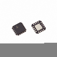
EL1511CLZ Intersil, EL1511CLZ Datasheet - Page 15

EL1511CLZ
Manufacturer Part Number
EL1511CLZ
Description
IC LINE DRIVER ADSL/VDSL 16-QFN
Manufacturer
Intersil
Type
Driverr
Datasheet
1.EL1511CL.pdf
(18 pages)
Specifications of EL1511CLZ
Number Of Drivers/receivers
1/0
Protocol
DSL
Voltage - Supply
5 V ~ 15 V
Mounting Type
Surface Mount
Package / Case
16-VQFN Exposed Pad, 16-HVQFN, 16-SQFN, 16-DHVQFN
Lead Free Status / RoHS Status
Lead free / RoHS Compliant
Available stocks
Company
Part Number
Manufacturer
Quantity
Price
Part Number:
EL1511CLZ
Manufacturer:
INTERSIL
Quantity:
20 000
performance section of the data sheet. When driving a load,
a large portion (about 50%) of the quiescent current
becomes output load current:
PD
where:
Assuming a maximum ambient temperature of 85°C and
keeping the junction temperature less than 150°C, the
maximum thermal resistance from junction to ambient
required is:
With proper layout, the EL1511CS package can achieve
47°C/W, well below the thermal resistance required by the
application.
PCB Layout Considerations for Thermal Packages
The EL1511 die is packaged in two different thermal efficient
packages, the 16 Ld SO and 16 Ld QFN packages. The 16
Ld SO package has the same dimensions as standard 0.15"
wide narrow body 16 Ld SO package with a special fused
lead frame that extends out through the center ground pins.
Both packages can use PCB surface metal vias areas and
internal ground planes, to spread heat away from the
package. The larger the PCB area the lower the junction
temperature of the device will be. In XDSL applications,
multiple layer circuit boards with internal ground plane are
generally used. 13 mil vias are recommended to connect the
metal area under the device with the internal ground plane.
Examples of the PCB layouts are shown in the figures below
that result in thermal resistance θ
package and 47°C/W for the SO package. The thermal
resistance is obtained with the EL1511CL and CS demo
boards. The demo board is a 4-layer board built with 2oz.
copper and has a dimension of 4in
follow the thermal layout guideline to achieve these results.
A separate Application Note for the QFN package and layout
recommendations is also available.
Θ
From
AFE
JA
=
PD = 338mW
=
T
12
T
X
X
150 85
--------------------- -
338mW
+
-
×
2R
464
(
6.6mA
–
G
=
+
+
1.5k
-
1.5k
-
192°C/W
R
R
×
F
F
V
V
V
V
50% )
S
S
S
S
+
-
+
-
+
(
12V
12.5
12.5
R
R
15
T
T
–
JA
2
2
×
. Note, the user must
of 37°C/W for the QFN
0.705 )
TXFR
1:2
×
28.2mA
100
EL1511
INTERNAL GROUND PLANE (16 Ld QFN)
INTERNAL GROUND PLANE (16 Ld SO)
TOP (16 Ld QFN)
TOP (16 Ld SO)
April 10, 2007
FN7016.2


