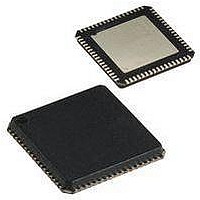
AT90USB1287-16MU Atmel, AT90USB1287-16MU Datasheet - Page 23

AT90USB1287-16MU
Manufacturer Part Number
AT90USB1287-16MU
Description
Microcontrollers (MCU) 128kB Flash 4kB EEPROM 48 I/O Pins
Manufacturer
Atmel
Datasheet
1.AT90USB1287-16MU.pdf
(30 pages)
Specifications of AT90USB1287-16MU
Data Bus Width
8 bit
Program Memory Type
Flash
Program Memory Size
128 KB
Data Ram Size
8 KB
Interface Type
2-Wire, SPI, USART
Maximum Clock Frequency
16 MHz
Number Of Programmable I/os
48
Number Of Timers
4
Operating Supply Voltage
2.7 V to 5.5 V
Maximum Operating Temperature
+ 85 C
Mounting Style
SMD/SMT
Package / Case
QFN-64
Minimum Operating Temperature
- 40 C
On-chip Adc
10 bit
Lead Free Status / Rohs Status
Details
Other names
AT90USB1287-MU
Available stocks
Company
Part Number
Manufacturer
Quantity
Price
Part Number:
AT90USB1287-16MU
Manufacturer:
ATMEL/爱特梅尔
Quantity:
20 000
7593GS–AVR–03/08
5.
4.
3. Spike on TWI pins when TWI is enabled
2. High current consumption in sleep mode
1. Asynchronous timer interrupt wake up from sleep generates multiple interrupts
The VSession valid threshold voltage is internally connected to VBus_Valid (4.4V approx.).
That causes the device to attach to the bus only when Vbus is greater than VBusValid
instead of V_Session Valid. Thus if VBUS is lower than 4.4V, the device is detached.
Problem fix/workaround
According to the USB power drop budget, this may require connecting the device toa root
hub or a self-powered hub.
The average USB signal rate may sometime be measured out of the USB specifications
(12MHz ±30kHz) with short frames. When measured on a long period, the average signal
rate value complies with the specifications. This bit rate deviation does not generates com-
munication or functional errors.
Problem fix/workaround
None.
In USB device and host mode, once a 5V level has been detected to the VBUS pad, a resid-
ual level (about 3V) can be measured on the VBUS pin.
Problem fix/workaround
None.
100 ns negative spike occurs on SDA and SCL pins when TWI is enabled.
Problem Fix/workaround
No known workaround, enable AT90USB64/128 TWI first versus the others nodes of the
TWI network.
If a pending interrupt cannot wake the part up from the selected mode, the current consump-
tion will increase during sleep when executing the SLEEP instruction directly after a SEI
instruction.
Problem Fix/workaround
Before entering sleep, interrupts not used to wake up the part from the sleep mode should
be disabled.
If the CPU core is in sleep and wakes-up from an asynchronous timer interrupt and then go
back in sleep again it may wake up multiple times.
Problem Fix/workaround
A s o ft wa r e wo r k ar o un d i s to w ai t wi t h pe r fo r mi n g th e s l ee p i n st r uc t io n u nt i l
TCNT2>OCR2+1.
UBS signal rate
VBUS residual level
AT90USB64/128
23


