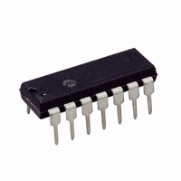
MCP2120-I/P Microchip Technology, MCP2120-I/P Datasheet - Page 11

MCP2120-I/P
Manufacturer Part Number
MCP2120-I/P
Description
IC ENCODER/DECODR INFRARED 14DIP
Manufacturer
Microchip Technology
Type
Infrared Encoder/Decoderr
Specifications of MCP2120-I/P
Package / Case
14-DIP (0.300", 7.62mm)
Voltage - Supply, Analog
2.5 V ~ 5.5 V
Voltage - Supply, Digital
2.5 V ~ 5.5 V
Mounting Type
Through Hole
Maximum Operating Temperature
+ 85 C
Minimum Operating Temperature
- 40 C
Mounting Style
Through Hole
Ic Function
Infrared Encoder/Decoder
Supply Voltage Range
2.5V To 5.5V
Operating Temperature Range
-40°C To +85°C
Digital Ic Case Style
DIP
No. Of Pins
14
Leaded Process Compatible
No
Rohs Compliant
Yes
Lead Free Status / RoHS Status
Lead free / RoHS Compliant
For Use With
MCP212XDM - BOARD DEVELOPMENT IRDA
Applications
-
Lead Free Status / Rohs Status
Lead free / RoHS Compliant
Available stocks
Company
Part Number
Manufacturer
Quantity
Price
Company:
Part Number:
MCP2120-I/P
Manufacturer:
ROHM
Quantity:
1 400
Part Number:
MCP2120-I/P
Manufacturer:
MICROCHIP/微芯
Quantity:
20 000
4.0
Absolute Maximum Ratings†
Ambient Temperature under bias ........................................................................................................... –40°C to +125°C
Storage Temperature ............................................................................................................................. –65°C to +150°C
Voltage on V
Voltage on RESET with respect to V
Voltage on all other pins with respect to V
Total Power Dissipation
Max. Current out of V
Max. Current into V
Input Clamp Current, I
Output Clamp Current, I
Max. Output Current sunk by any Output pin..........................................................................................................25 mA
Max. Output Current sourced by any Output pin.....................................................................................................25 mA
© 2007 Microchip Technology Inc.
†
is a stress rating only and functional operation of the device at those or any other conditions above those indicated in
the operation listings of this specification is not implied. Exposure to maximum rating conditions for extended periods
may affect device reliability.
NOTICE: Stresses above those listed under "Maximum Ratings" may cause permanent damage to the device. This
Note 1: Power Dissipation is calculated as follows:
ELECTRICAL CHARACTERISTICS
P
DD
DIS
with respect to V
= V
DD
DD
SS
IK
pin .....................................................................................................................................125 mA
x {I
OK
(1)
pin ..................................................................................................................................150 mA
(VI < 0 or VI > V
DD
...................................................................................................................................700 mW
(V0 < 0 or V0 > V
- ∑ I
SS
OH
.....................................................................................................................0 to +7V
SS
} + ∑ {(V
.............................................................................................................0 to +14V
DD
SS
) ................................................................................................................... ±20 mA
................................................................................. –0.6V to (V
DD
DD
)............................................................................................................. ±20 mA
-V
OH
) x I
OH
} + ∑(V
OL
x I
OL
)
MCP2120
DS21618B-page 11
DD
+ 0.6V)


