MCP2120-I/P Microchip Technology, MCP2120-I/P Datasheet - Page 7

MCP2120-I/P
Manufacturer Part Number
MCP2120-I/P
Description
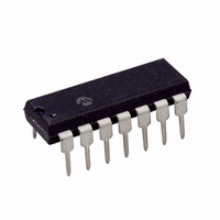
IC ENCODER/DECODR INFRARED 14DIP
Manufacturer
Microchip Technology
Type
Infrared Encoder/Decoderr
Specifications of MCP2120-I/P
Package / Case
14-DIP (0.300", 7.62mm)
Voltage - Supply, Analog
2.5 V ~ 5.5 V
Voltage - Supply, Digital
2.5 V ~ 5.5 V
Mounting Type
Through Hole
Maximum Operating Temperature
+ 85 C
Minimum Operating Temperature
- 40 C
Mounting Style
Through Hole
Ic Function
Infrared Encoder/Decoder
Supply Voltage Range
2.5V To 5.5V
Operating Temperature Range
-40°C To +85°C
Digital Ic Case Style
DIP
No. Of Pins
14
Leaded Process Compatible
No
Rohs Compliant
Yes
Lead Free Status / RoHS Status
Lead free / RoHS Compliant
For Use With
MCP212XDM - BOARD DEVELOPMENT IRDA
Applications
-
Lead Free Status / Rohs Status
Lead free / RoHS Compliant
Available stocks
Company
Part Number
Manufacturer
Quantity
Price
Company:
Part Number:
MCP2120-I/P
Manufacturer:
ROHM
Quantity:
1 400
Part Number:
MCP2120-I/P
Manufacturer:
MICROCHIP/微芯
Quantity:
20 000
2.5
When the UART receives data to be transmitted, the
data needs to be modulated. This modulated signal
drives the IR transceiver module.
encoding of the modulated signal.
Each bit time is comprised of 16-bit clocks. If the value
to be transmitted (as determined by the TX pin) is a
logic low, then the TXIR pin will output a low level for
7-bit clock cycles, a logic high level for 3-bit clock
cycles, and then the remaining 6-bit clock cycles will be
low. If the value to transmit is a logic high, then the
TXIR pin will output a low level for the entire 16-bit clock
cycles.
FIGURE 2-2:
FIGURE 2-3:
© 2007 Microchip Technology Inc.
BITCLK
(CLK)
BITCLK
RXIR
RX
TX
TXIR
Modulation
Start Bit
16 CLK
Start Bit
16 CLK
Encoding
Decoding
≥ 1.6 µs
0
16 CLK
8 CLK
7 CLK
0
12 Tosc
Figure 2-2
Data bit 0
Data bit 0
13 CLK (or ≤ 50.5 µs typical)
1
16 CLK
shows the
1
Data bit 1
Data bit 1
0
16 CLK
0
Data bit 2
2.6
The modulated signal from the IR transceiver module
needs to be demodulated to form the received data. As
demodulation occurs, the bit value is placed on the RX
pin in UART format.
the modulated signal.
Each bit time is comprised of 16 bit clocks. If the value
to be received is a logic low, then the RXIR pin will be
a low level for the first 3-bit clock cycles, and then the
remaining 13-bit clock cycles will be high. If the value to
be received is a logic high, then the RXIR pin will be a
high level for the entire 16-bit clock cycles. The level on
the RX pin will be in the appropriate state for the entire
16 clock cycles.
Data bit 2
0
16 CLK
Demodulation
0
Data bit ...
Data bit...
1
Figure 2-3
16 CLK
1
MCP2120
shows the decoding of
0
16 CLK
DS21618B-page 7
0


