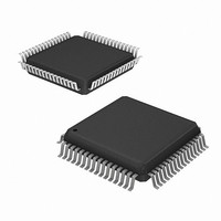
HMP8156ACNZ Intersil, HMP8156ACNZ Datasheet - Page 31

HMP8156ACNZ
Manufacturer Part Number
HMP8156ACNZ
Description
IC VIDEO ENCODER NTSC/PAL 64MQFP
Manufacturer
Intersil
Type
NTSC/PAL Encoderr
Datasheet
1.HMP8156ACNZ.pdf
(34 pages)
Specifications of HMP8156ACNZ
Applications
Multimedia, Video Editing
Voltage - Supply, Analog
4.75 V ~ 5.25 V
Voltage - Supply, Digital
4.75 V ~ 5.25 V
Mounting Type
Surface Mount
Package / Case
64-MQFP, 64-PQFP
Lead Free Status / RoHS Status
Lead free / RoHS Compliant
Available stocks
Company
Part Number
Manufacturer
Quantity
Price
Typical Performance Curves
Application Information
Vertical Blanking Information Encoding
VBI data such as teletext may be encoded on any line by
driving the pixel inputs with appropriate data. For YCbCr
input modes, Cb and Cr should equal 128 to disable the
color information. For RGB input modes, R, G, and B should
always have the same value to disable the color information.
Vertical blanking must be negated on the first scan line
containing VBI information. If there are unused scan lines
between the VBI data and active video, BLANK must remain
on and the pixel inputs should be set to the black level.
Video Insertion Test Signalsy
Video test signals may be generated by driving the pixel
inputs with appropriate data. Most of the video test signals
require using YCbCr pixel data.
Vertical blanking must be negated on the first scan line
containing video test signals. If there are unused scan lines
between test signal data and active video, BLANK must
remain off and the pixel inputs should be set to the black level.
PCB Considerations
A PCB board with a minimum of 4 layers is recommended, with
layers 1 and 4 (top and bottom) for signals and layers 2 and 3
for power and ground. The PCB layout should implement the
lowest possible noise on the power and ground planes by
providing excellent decoupling. PCB trace lengths between
groups of V
Component Placement
The optimum layout places the HMP8154/HMP8156A at the
edge of the PCB and as close as possible to the video output
connector. External components should be positioned as
close as possible to the appropriate pin, ideally such that
traces can be connected point to point. Chip capacitors are
recommended where possible, with radial lead ceramic
capacitors the second-best choice.
FIGURE 34. H SYNC JITTER IN A FRAME (PAL)
AA
and GND pins should be as short as possible.
31
(Continued)
HMP8154, HMP8156A
Traces containing digital signals should not be routed over,
under, or adjacent to the analog output traces to minimize
crosstalk. If this is not possible, coupling can be minimized
by routing the digital signals at a 90 degree angle to the ana-
log signals. The analog output traces should also not cross
over or under the V
quency power supply rejection.
Power and Ground Planes
A common ground plane for all devices, including the
HMP8154/HMP8156A, is recommended. However, placing the
encoder on an electrically connected GND peninsula reduces
noise levels. All GND pins on the HMP8154/HMP8156A must
be connected to the ground plane. Typical power and ground
planes are shown in Figure 36.
The small connection between the ground areas should be
made wide enough so that most of the encoders digital inputs
can be routed over or under it. It is especially important that the
CLK and CLK2 signals cross through the connection.
The HMP8154/HMP8156A should have its own power plane
that is isolated from the common power plane of the board,
with a gap between the two power planes of at least 1/8 inch.
All V
to this isolated power plane.
The HMP8154/HMP8156A power plane should be connected
to the board’s normal V
a low-resistance ferrite bead, such as a Ferroxcube 5659065-
3B, Fair-Rite 2743001111, or TDK BF45-4001. The ferrite bead
provides resistance to switching currents, improving the
performance of HMP8154/HMP8156A. A single, large
capacitor should also be used between the
HMP8154/HMP8156A power plane and the ground plane to
control low-frequency power supply ripple.
AA
FIGURE 35. SCH PHASE MEASUREMENT (PAL)
pins of the HMP8154/HMP8156A must be connected
CC
CC
power plane to maximize high-fre-
power plane at a single point though
August 20, 2009
FN4343.5


