SAA7327H/T/M2B,557 NXP Semiconductors, SAA7327H/T/M2B,557 Datasheet - Page 10

SAA7327H/T/M2B,557
Manufacturer Part Number
SAA7327H/T/M2B,557
Description
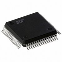
IC DIGITAL/CD DAC DECODER 64QFP
Manufacturer
NXP Semiconductors
Type
Audio Decoderr
Datasheet
1.SAA7327HTM2B557.pdf
(68 pages)
Specifications of SAA7327H/T/M2B,557
Voltage - Supply, Digital
3 V ~ 3.6 V
Mounting Type
Surface Mount
Package / Case
64-QFP
Lead Free Status / RoHS Status
Lead free / RoHS Compliant
Applications
-
Voltage - Supply, Analog
-
Lead Free Status / RoHS Status
Lead free / RoHS Compliant, Lead free / RoHS Compliant
Other names
935268128557
SAA7327HBG
SAA7327HBG
SAA7327HBG
SAA7327HBG
Available stocks
Company
Part Number
Manufacturer
Quantity
Price
Company:
Part Number:
SAA7327H/T/M2B,557
Manufacturer:
NXP Semiconductors
Quantity:
10 000
Philips Semiconductors
7.2
The crystal oscillator is a conventional 2-pin design
operating between 8 and 35 MHz. This oscillator is
capable of operating with ceramic resonators and with
both fundamental and third overtone crystals. External
components should be used to suppress the fundamental
output of the third overtone crystals as shown in
Figs 3 and 4. Typical oscillation frequencies required are
8.4672, 16.9344 or 33.8688 MHz depending on the
internal clock settings used and whether or not the clock
multiplier is enabled.
2000 Jun 26
handbook, halfpage
handbook, halfpage
Digital servo processor and Compact Disc
decoder with integrated DAC for video CD (CD7 II)
Fig.3 8.4672 MHz fundamental configuration.
Crystal oscillator
Fig.4 33.8688 MHz overtone configuration.
MGS247
CROUT
CROUT
SAA7327
SAA7327
33 pF
10 pF
OSCILLATOR
OSCILLATOR
33.8688 MHz
8.4672 MHz
33 pF
10 pF
CRIN
CRIN
3.3 H
MGS246
1 nF
10
7.3
The SAA7327 has an integrated slice level comparator
which can be clocked by the crystal frequency clock, or
4 times the crystal frequency clock (if SELPLL is set HIGH
while using a 16.9344 MHz crystal and register 4 is set to
0XXX), or 8 times the crystal frequency clock (if SELPLL is
set HIGH while using an 8.4672 MHz crystal, and
register 4 is set to 0XXX). The slice level is controlled by
an internal current source applied to an external capacitor
under the control of the Digital Phase-Locked
Loop (DPLL).
Regeneration of the bit clock is achieved with an internal
fully digital PLL. No external components are required and
the bit clock is not output. The PLL has two registers
(8 and 9) for selecting bandwidth and equalization.
The PLL response is shown in Fig.5.
For certain applications an off-track input is necessary.
This is internally connected from the servo part (its polarity
can be changed by the foc_parm1 parameter), but may be
input via the V1 pin if selected by register C. If this flag is
HIGH, the SAA7327 will assume that its servo part is
following on the wrong track, and will flag all incoming
HF data as incorrect.
handbook, halfpage
1, 2 and 3 are programmable via decoder register 8.
response
loop
PLL
Data slicer and clock regenerator
Fig.5 Digital PLL loop response.
1. PLL integrator
2. PLL bandwidth
Product specification
3. PLL, LPF
SAA7327
MGS178
f


