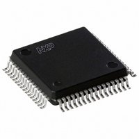
SAA7327H/T/M2B,557 NXP Semiconductors, SAA7327H/T/M2B,557 Datasheet - Page 14

SAA7327H/T/M2B,557
Manufacturer Part Number
SAA7327H/T/M2B,557
Description
IC DIGITAL/CD DAC DECODER 64QFP
Manufacturer
NXP Semiconductors
Type
Audio Decoderr
Datasheet
1.SAA7327HTM2B557.pdf
(68 pages)
Specifications of SAA7327H/T/M2B,557
Voltage - Supply, Digital
3 V ~ 3.6 V
Mounting Type
Surface Mount
Package / Case
64-QFP
Lead Free Status / RoHS Status
Lead free / RoHS Compliant
Applications
-
Voltage - Supply, Analog
-
Lead Free Status / RoHS Status
Lead free / RoHS Compliant, Lead free / RoHS Compliant
Other names
935268128557
SAA7327HBG
SAA7327HBG
SAA7327HBG
SAA7327HBG
Available stocks
Company
Part Number
Manufacturer
Quantity
Price
Company:
Part Number:
SAA7327H/T/M2B,557
Manufacturer:
NXP Semiconductors
Quantity:
10 000
Philips Semiconductors
7.6
The SAA7327 has a 8 frame FIFO. The error corrector is
a t = 2, e = 4 type, with error corrections on both C1
(32 symbol) and C2 (28 symbol) frames. Four symbols are
used from each frame as parity symbols. This error
corrector can correct up to two errors on the C1 level and
up to four errors on the C2 level.
The error corrector also contains a flag processor. Flags
are assigned to symbols when the error corrector cannot
ascertain if the symbols are definitely good. C1 generates
output flags which are read after (de-interleaving) by C2,
to help in the generation of C2 output flags.
The C2 output flags are used by the interpolator for
concealment of uncorrectable errors. They are also output
via the EBU signal (DOBM). The EF output will flag bytes
in error in both audio and CD-ROM modes.
2000 Jun 26
handbook, full pagewidth
Digital servo processor and Compact Disc
decoder with integrated DAC for video CD (CD7 II)
n = disc speed.
n = disc speed.
FIFO and error corrector
F8
W96
33.9/n s
200/n s
min
11.3/n
Fig.9 Subcode format and timing on pin V4.
F1
s
1
Fig.10 Flag output timing diagram.
11.3/n
F2
Q
s
F3
R
F4
S
F5
14
T
7.6.1
The flags output pin CFLG shows the status of the error
corrector and interpolator and is updated every frame
(7.35
on the CFLG pin as illustrated in Fig.10. This signal shows
the status of the error corrector and interpolator.
The first flag bit, F1, is the absolute time sync signal, the
FIFO-passed subcode sync and relates the position of the
subcode sync to the audio data (DAC output). This flag
may also be used in a super FIFO or in the synchronization
of different players. The output flags can be made
available at bit 4 of the EBU data format (LSB of the 24-bit
data word), if selected by decoder register A.
F6
U
F7
V
n kHz). In the SAA7327 chip a 1-bit flag is present
F
F8
LAGS OUTPUT
W
33.9/n s
11.3/n s min
90/n s max
(CFLG)
MBG425
F1
1
MBG401
Q
Product specification
SAA7327


