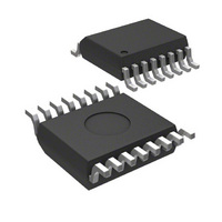
MIC74YQS TR Micrel Inc, MIC74YQS TR Datasheet - Page 7

MIC74YQS TR
Manufacturer Part Number
MIC74YQS TR
Description
IC I/O EXPANDER I2C 8B 16QSOP
Manufacturer
Micrel Inc
Datasheet
1.MIC74YQS.pdf
(18 pages)
Specifications of MIC74YQS TR
Interface
I²C, SMBus
Number Of I /o
8
Interrupt Output
Yes
Voltage - Supply
2.7 V ~ 3.6 V
Operating Temperature
-40°C ~ 85°C
Mounting Type
Surface Mount
Package / Case
16-QSOP
Lead Free Status / RoHS Status
Lead free / RoHS Compliant
Frequency - Clock
-
Other names
MIC74YQSTR
MIC74YQSTR
MIC74YQSTR
Functional Diagram
Functional Description
Pin Descriptions
VDD
Power supply input connection. See “Operating Ratings.”
GND
Ground or return connection for all MIC74 functions.
CLK
An CLK signal is provided by the host (master) and is
common to all devices on the bus. The CLK signal
controls all transactions in both directions on the bus and
is applied to each MIC74 at the CLK pin.
DATA
Serial data is bidirectional and is common to all devices
on the bus. The MIC74’s DATA output is open-drain.
The DATA line requires one external pull-up resistor or
current source per system that can be located anywhere
along the line.
A2, A1, A0
An MIC74 responds to its own unique address which is
assigned using the A0–A2 pins. A0–A2 set the three
LSBs (least significant bits) of the MIC74’s 7-bit slave
address. The three address pins allow eight unique
MIC74 addresses in a system. When the MIC74’s
address matches an address received in the serial bit
stream, communication is initiated.
Micrel, Inc.
October 2006
STATUS_READn
OUT_CFGn
(OUTPUT)
STATUSn
(INPUT)
DATAn
DATAn
DIRn
INTn
IMn
Typical I/O Port (Fan Speed Control Logic Not Shown)
Q
Q R
S
7
DETECT
A2, A1 and A0 should be connected to GND or VDD.
The state of these pins is sampled only once at device
power-on. New slave addresses are not accepted unless
the MIC74 is powered off then on.
Alert Response Address
The MIC74 also responds to the ARA (Alert Response
Address). The ARA is used by the master (host) to
request the address of a slave that has provided an
interrupt to the master via the /ALERT line.
The ARA is a single address (0001 100) common to all
slaves and is described in more detail under “Interrupt
Generation” with related information under “/ALERT.”
Also see Figure 7.
EDGE
A2
0
0
0
0
1
1
1
1
Inputs
A1
0
0
1
1
0
0
1
1
Table 1. MIC74 Address Configuration
GND
V
A0
0
1
0
1
0
1
0
1
DD
Pn (typical I/O port)
010 0000
010 0001
010 0010
010 0011
010 0100
010 0101
010 0110
010 0111
Bianary
MIC74 Slave Address
b
b
b
b
b
b
b
b
M9999-101006
Hex
20
21
22
23
24
25
26
27
MIC74
h
h
h
h
h
h
h
h


