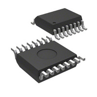
MIC74YQS TR Micrel Inc, MIC74YQS TR Datasheet - Page 9

MIC74YQS TR
Manufacturer Part Number
MIC74YQS TR
Description
IC I/O EXPANDER I2C 8B 16QSOP
Manufacturer
Micrel Inc
Datasheet
1.MIC74YQS.pdf
(18 pages)
Specifications of MIC74YQS TR
Interface
I²C, SMBus
Number Of I /o
8
Interrupt Output
Yes
Voltage - Supply
2.7 V ~ 3.6 V
Operating Temperature
-40°C ~ 85°C
Mounting Type
Surface Mount
Package / Case
16-QSOP
Lead Free Status / RoHS Status
Lead free / RoHS Compliant
Frequency - Clock
-
Other names
MIC74YQSTR
MIC74YQSTR
MIC74YQSTR
Fan Start-Up
Any time the fan speed register contains zero (fan is off)
and then a nonzero value is written to FAN_SPEED, the
/FS[2:0] and /SHDN outputs will assume the highest fan
speed state for approximately one second (t
Following this interval, the state of the fan speed control
outputs will assume the value indicated by the contents
of FAN_SPEED. This insures that the fan will start
reliably when low speed operation is desired. The t
interval is generated by an internal oscillator and
counters. At the end of t
down to reduce overall power consumption.
Proper sequencing of the /FS[2:0] and /SHDN signals is
performed by the MIC74’s internal logic state machine.
When activating the fan from the off state, the /FS[2:0]
lines change state first, then, after a delay equal to one-
MIC74
Micrel, Inc.
October 2006
Figure 1. Fan Speed Control Application
R
DEV_CONFIG
FAN_SPEED
PULL-UP
INT_MASK
OUT_CFG
Register
STATUS
Name
DATA
/SHDN
/FS2
/FS1
/FS0
DIR
START
R
R
R
/SHDN
VIN
F2
F2
F2
Regulator
Device Configuration
General-Purpose I/O
Output Configuration
, this oscillator is powered
GND
Interrupt Status
Interrupt Mask
VOUT
Description
I/O Direction
Fan Speed
Register
FB
R
R
FB
MIN_SPEED
Table 2. Register Summary
START
0000 0001
0000 0011
0000 0101
0000 0000
0000 0010
0000 0100
0000 0110
START
FAN
Binary
).
Address
9
b
b
b
b
b
b
b
half of t
when the fan is shutdown (zero is written to
FAN_SPEED), the /SHDN pin is deasserted first. The
/FS[2:0] lines are subsequently deasserted after a delay
of 1⁄2t
following the t
timing relationships are illustrated in Figure 2.
Interrupt Generation
Assuming that any or all of the I/O’s are configured as
inputs, the MIC74 will reflect the occurrence of an input
change in the corresponding bit in the status register,
STATUS. This action cannot be masked. An input
change will only generate an interrupt to the host if
interrupts are properly configured and enabled.
The MIC74 can operate in either polled mode or interrupt
mode. In the case of polled operation, the host
periodically reads the contents of STATUS to determine
the device state. The act of reading STATUS clears its
contents. Repeating events which have occurred since
the last read from STATUS will not be discernable to the
host.
Interrupts are only generated if the global interrupt
enable bit, IE, in the DEV_CFG register is set. The
/ALERT signal will be asserted (driven low) when an
interrupt is generated. The MIC74 expects to be
interrogated using the ARA when it has generated an
interrupt output. Once it has successfully responded to
the ARA (Alert Response Address), the /ALERT output
will be deasserted. The contents of the status register
will not be cleared until it is read using a read byte
operation.
If a given system does not wish to use the SMBus ARA
protocol for reporting interrupts, the system may simply
poll the contents of the status register after detecting an
interrupt on /ALERT. This action will clear the contents of
STATUS and cause /ALERT to be deasserted. Reading
the status register is an acceptable substitute for using
the ARA protocol. Presumably, however, it will involve
higher system overhead since all the devices on the bus
must be polled to determine which one generated the
interrupt.
Hex
00
01
02
03
04
05
06
h
h
h
h
h
h
h
START
START
8-bit read/write
8-bit read/write
8-bit read/write
8-bit read/write
8-bit read/write
8-bit read/write
Operations
. The internal oscillator is also powered down
Available
8-bit read
, the /SHDN pin is deasserted. Conversely,
START
/2 interval at fan shut-down. These
0000 0000
0000 0000
0000 0000
0000 0000
0000 0000
1111 1111
0000 0000
Power-On Default
Binary
b
b
b
b
b
b
b
Hex
FF
00
00
00
00
00
00
M9999-101006
h
h
h
h
h
h
h
MIC74


